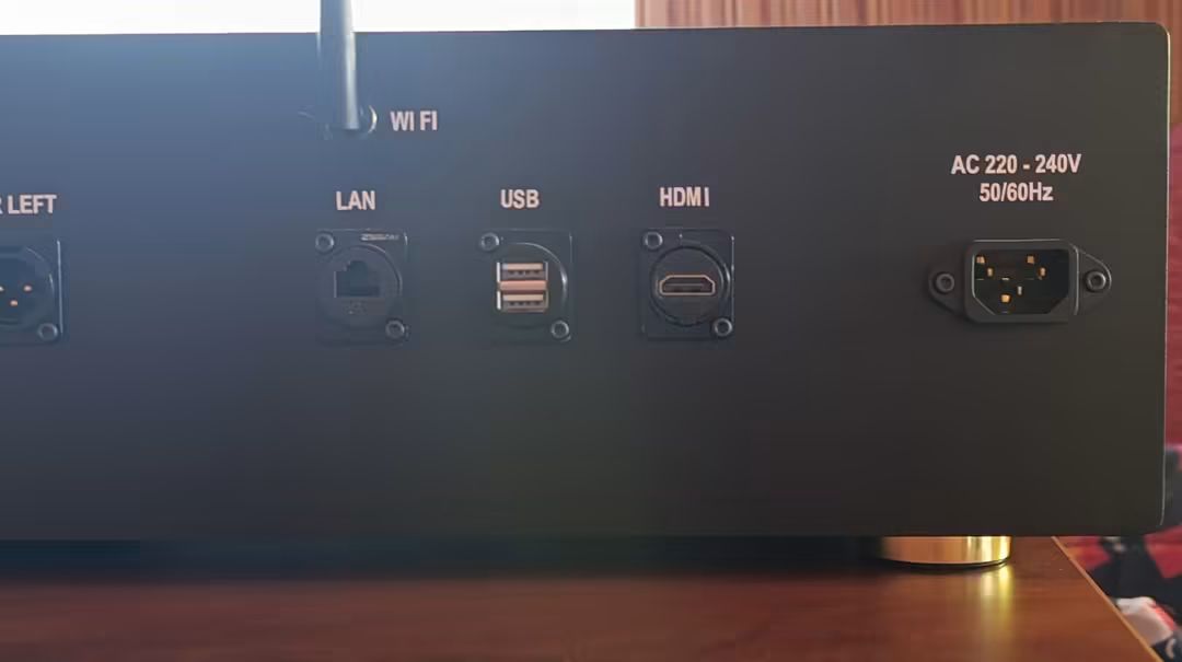
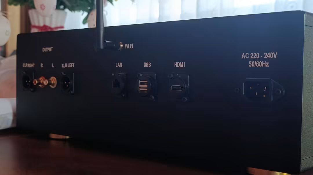
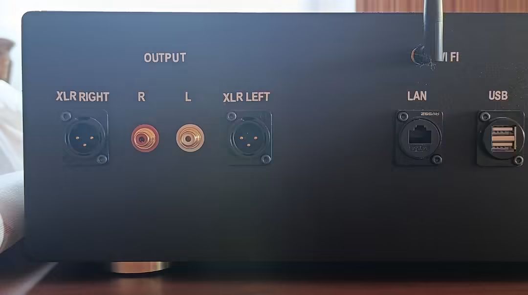
RPI 5 Dont start with GPIO with linear supply

Hi guys need help
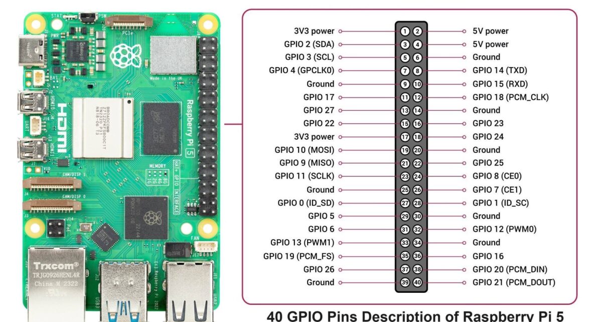
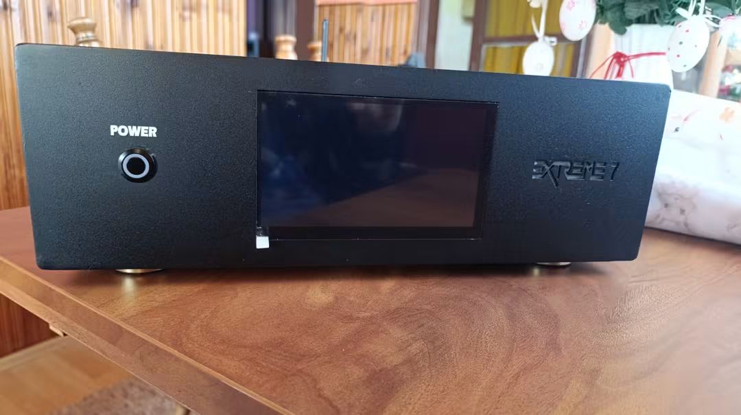
i have a linear supply with 5V 5A and connect my RPI5 with GPIO (i2S pin) with pin 2(5V) & pin 6(GND), now, when i click the button on rpi5 its work, when i shut down try to start, the light button is red till i again open my Streamer and push again the button on him ???
when i put the RPI USB supply its start every time, please help

----------------------------- Delete here & above before posting below -----------------

It sounds like your 5V linear power supply is powering the Pi correctly, but it is not supporting the Raspberry Pi 5’s power management the same way the official USB-C supply does.

When powered through pins 2 (5V) and 6 (GND) on the GPIO header, the Pi 5 can run normally, but after a software shutdown the PMIC (power management controller) is not able to sequence the power correctly for the next startup.

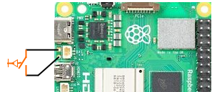
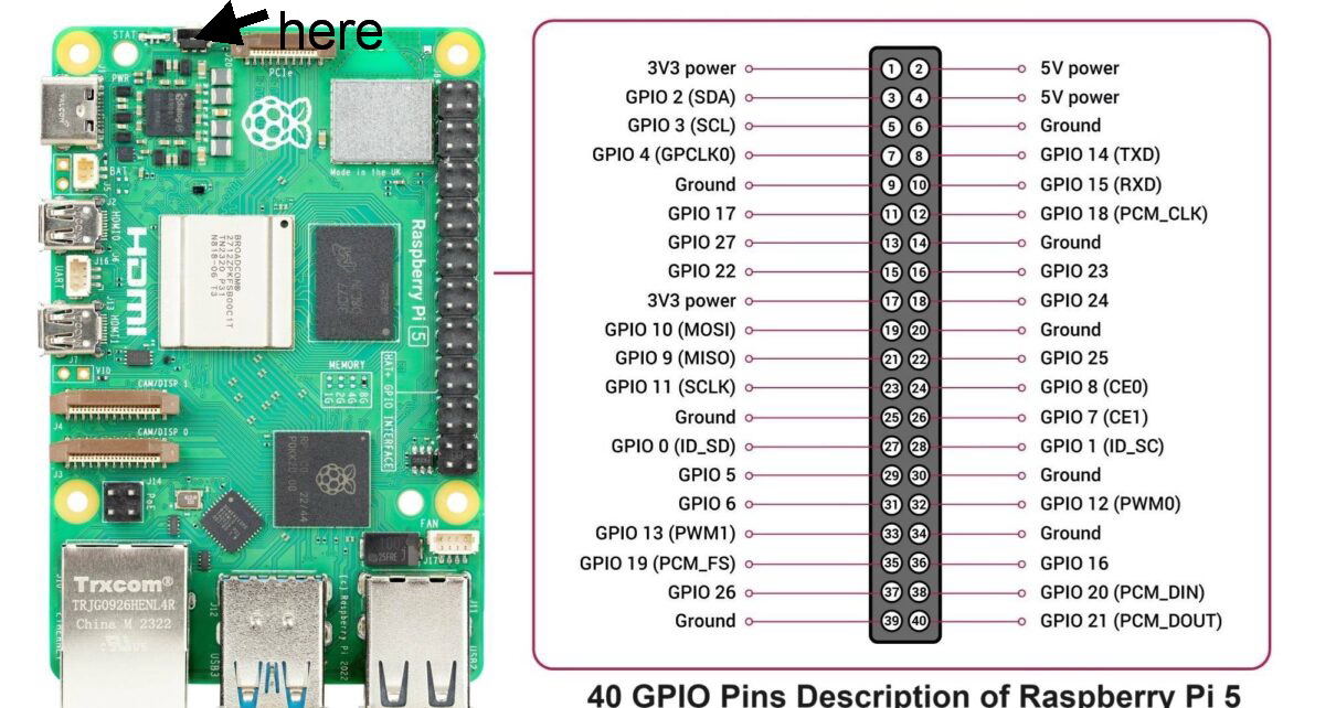
You might build in a power button on the back of your device, so you have the switch externaly.
image

thx for you help , i must say that the linear supply is MOSFET , but i think that not a problem…

but RPI 5 has a power button

I make streamer dac


yes and you can connect an external power button on the points I gave you. Which will do the same as the on board button, which you need to press now.

On RPI 4 works in gpio on pins but on rpi5 its also but its red i always must to strat rpi 5 with the button on him , make restart its work, when i shut it down , and turn it again, it not will startet Automatic how with the usb original power supply, just when i again tap the power button on him its work

I see on YouTube so one just solder the 2 pins i am scared the to do this why that ???
On rpi4 works no problem on rpi5 works but only when i startet when i klik on him its works??? I search on YouTube bit i don find everyth usefull???

You might try this, not sure if it solves the power up issue, but give it a try:
Run from putty (ssh session):
sudo -E rpi-eeprom-config --edit

Add to the bottom of the file:
PSU_MAX_CURRENT=5000

Save it and reboot.

Check after reboot, if new parameter has loaded:
vcgencmd get_config int | grep PSU_MAX_CURRENT

This bypasses the voltage checks on the rPi, by telling it there is an adequate PSU connected.

Also check if the voltage on the GPIO is indeed 5V and not lower!!!

I looked with a volmeter and oscilloscope its 5.1V , i think i i has found a solution, when not i write again , thx my friend

no i think i had a solution but no, its same again when i turn off my streamer dac …RPI5 i s turned off untill i open and manual press the button on him, then his start turn on monitor, you can do what ever ,lisening music or stream what ever… i restartet , its worked , i shut him down , …again the same game …open , push red button on RPI5 and his work again…i cheked severly times my linear supply its always 5,1V and 5A…can everybody help???
when i put original supply RPI5 with usb C work every time…???

Hey @djoksim1,

First, to be clear: this is not a Volumio problem. This is generic Raspberry Pi 5 hardware behavior. It happens with any OS and is a problem as old as the Pi 5 release itself - reports on the official Raspberry Pi forums date back to December 2023, weeks after launch.

What is happening:

The Pi 5 has a power management chip (PMIC) that the Pi 4 does not have. This PMIC has an undervoltage lockout: if the 5V rail rises too slowly when power is applied, the PMIC latches into STANDBY state and waits for the power button. The critical window is the rise from about 3.5V to 4.1V. The official USB-C supply ramps up in under 40ms. A linear supply with large output capacitors ramps up much slower when you switch on your streamer, so the PMIC locks out and you see the solid red LED until you press the button.

This is why:

  • Your Pi 4 works fine with the same supply. The Pi 4 has no PMIC state machine. It simply boots whenever 5V is present, regardless of ramp speed.
  • Your voltage measurement shows 5.1V. The steady-state voltage is not the problem. The problem is how fast it gets there at switch-on.
  • The PSU_MAX_CURRENT setting did not help. That setting addresses current negotiation for USB boot, a different limitation. It has no effect on the rise-time lockout.

Sources (same symptom, same cause, discussed at length):

One user in the second thread proved it with a controlled test: enabling the supply output with leads connected to GPIO gave red LED and no boot. Hot-plugging the 5V lead with the supply already running (fast voltage edge) booted every time. Same supply, same Pi.

Since you have an oscilloscope, you can verify this yourself: measure how long your supply output takes to rise from 3.5V to 4.1V at switch-on. You will likely see it is far slower than the USB-C supply.

The solution:

@Wheaten already gave you the viable answer. The Pi 5 PCB has a dedicated unpopulated 2-pin 2.54mm footprint (J2, next to the battery connector) placed there by Raspberry Pi exactly for this purpose. Solder a 2-pin header or two wires there and connect a momentary push button on the back panel of your streamer. Pressing it does exactly the same as the onboard power button. This is what the YouTube video you found shows. There is nothing to be scared of - it is a designed-in feature of the board, not a hack. Two solder joints on through-hole pads, no risk to the Pi if you take normal care.

Alternative, if you want automatic start without any button: move your on/off switch to the DC side. Keep the linear supply permanently powered and switch its 5V output to the Pi instead of switching the mains. The Pi then sees a fast voltage edge and boots by itself, as proven in the hot-plug test above.

Kind Regards,

thx guys…now i understand
thx a lot

i found how to make it works on PRI5, it can not start on GPIO, you must make a cabel with USB C connector with Linear supply , its start every time and works much better than original supply…but Voltage no more than 5.07 - 5.10V , and 5A…any way…thx guys…now i can help you when you want a Linear supply to put on RPI5
THX again guys

Hey @djoksim1,

Good result, and thanks for reporting back with the solution.

Feeding the linear supply through the USB-C connector instead of the GPIO pins is a clean approach. It matches what others on the Raspberry Pi forums found with the same symptom: the same supply that fails on the GPIO pins boots reliably through the USB-C input. And your voltage discipline is correct - keep it at 5.07 to 5.10V, no higher.

Since you offered to help others: please do post your schematics with technical details and a short writeup. Cable construction, connector type, how you wired the USB-C plug, supply specs and voltage trim. There are plenty of streamer builders using linear supplies on the Pi 5 who will run into exactly this, and a documented working solution in this thread will save them the whole journey.

Kind Regards,

Peace of mind for all things Pi and power:
Leeloo

1 Like

Hey @LOVEANDFURY,

Could you clarify how this link relates to the topic of this thread? The discussion here is about the Pi 5 PMIC power-on behavior with linear supplies on the GPIO pins, and it has been resolved with a documented solution. Your product, as far as I can see, is a 3D printed case, not a power supply, so the connection is not obvious.

If the intent was to promote the Leeloo case, please keep that in your own product thread in DIY and Tweaks:

Bare product links in support threads without technical context read as advertising, and we would like to keep support threads focused on the problem being solved.

If the case does include something specifically relevant to this power-on issue, please explain it here with technical details - that would be a welcome contribution.

Kind Regards,

Hi @nerd , thank you for pointing it out, and I am sorry for making this mistake. I got carried away because I spend SOOOO much time exactly with this power management of the Pi. Also thank you for not “hanging” me from the tree :slight_smile: .

The technical context:
Connecting to the GPIOs bypasses the power management circuit of the Pi. What is this? It is not much in terms of components (up to 4), but when it is missing it causes all the problems described. Pi 3, 4, and 5 have different levels of implementations of such a power management circuit.

In general, to be complete, it needs:
A) 2 x 5.1k resistors for the USB PD(Power Delivery) handshake. This is for two reasons. 1) To tell a USB PD power supply “Hey there, I need only 5V 3A, not 20V 5A”).

///edit: this is wrong: And 2) These resistors make the connection “hot”. So for a linear power supply, the capacitors are then charged up, not starting from “cold”. Meaning no issues with the Voltage ramp up/rise-time.///.

///Update: I am curious if a problematic linear power supply would still work in the Leeloo circuit, for other reasons now unknown. Got to get my hands on one.///

B) A switch (a P-Channel MOSFET) that has the function to completely cut power to the Pi, not leaving it in standby.

/// this is wrong: Because from there the Pi 3 and 4 cannot turn on again.///

///this is correct: They can, with the GPIO03 or Global_EN to ground shorting, and the Pi 5 with its switch and PMIC///.

///Why I wrote it this way, because I forgot to write what I this was leading up to: If you make an implementation using the “Short GPIO03 to ground” function to restart, then you would need two buttons. One for turning on, one for initiating the shutdown. Otherwise it would restart when you want to shutdown.///

///update: Moreover: In standby/halt the 5V PINs are still on in all Pi generations, and this is not what you want if a HAT is attached to it and a FAN that is supposed to stop spinning when the device is turned off.///

C) One TVS Diode for ESD protection.
D) A Fuse for overcurrent protection.

A) and B) are needed for correct function. C) and D) is for safety. Pi 3, 4, and 5 do not have B). This is the reason why when doing software shut down all Pi generations “end up” in standby, with the red light on.

Note: Pi 3, 4, and 5 have different implementations and also each generation has different revisions of what functionality the power management circuit has, eg. here is an interesting read about what happened on the first Pi 4s.

The Leeloo is not only a case, but it is a case with PCB that has such a power management circuit implemented. All functions, ABCD. Therefore, connecting a power supply of any type, /// update: this is a wishful claim: just works./// To be confirmed.

It is possible to hand-build/solder such a power management circuit, with wires and THT components. It is fun to do. If you prefer not to do it, the Leeloo was made for this.
Thank you, and happy building, and any questions about Pi and Power management, happy to respond. It is a rabbit hole so deep I never expected it to be :slight_smile:
Timo

Note 1: Because of the rabbit hole (meaning unexpected issues lurk behind each turn) I cant say for certain that the linear power supply from @djoksim1 will work on the Leeloo. But from all I know, it should. Would love to test it, can I send you a unit for testing @djoksim1, or what is the name of the linear power supply you use maybe I can get my hands on it here in Berlin. Happy building
Note 2: In my excitement I forgot to mention an/the most important point. The power management circuit has just 4 components max, but to make it work with the Pi one has to build another thing, called a latching circuit. A great explanation about it is by Kevin Darrah here. For the brave at heart, it can be done with THT components. They key of this is that it allows the Pi to do a software shut down, sometimes called gentle shut down, or safe shutdown, and when its all done and good the Pi sends a signal to the latching circuit to cut the power. Software side it is a single line to the config.txt dtoverlay=gpio-poweroff,gpiopin=26(or any pin you chose for that function. But be careful here, the GPIOs have different default states and also cycle though high and low during startup. They end up in GPIO 0-8 pulled up to 3.3V, and ///edit: this was wrong: GPIO 7-27/// GPIO 9-27 pulled down to GND. It is a rabbit hole, but fun when it all works.

Hey @LOVEANDFURY,

Thanks for coming back with technical content and for taking the moderation note well. Since this thread will be found by future builders, the record needs to be precise. Some of your points are correct, one central claim is not, and one is wrong for the Raspberry Pi 5 specifically. References below so anyone can verify.

Facts are:

  • The 5.1k resistors are real and required. They are the Rd pull-downs on the CC1/CC2 lines defined in the USB Type-C Cable and Connector Specification (USB-IF). A sink must present Rd on CC to be recognized by a Type-C source. Reference: USB Type-C spec, sink CC termination Rd = 5.1k.
  • The Pi 4 rev 1.0 USB-C fault you linked (shared CC resistor, e-marked cables refusing to power the board) is real and was acknowledged by Raspberry Pi.
  • The external latch plus dtoverlay=gpio-poweroff technique is legitimate - for Pi 3 and Pi 4, which have no PMIC power switch. The Kevin Darrah video is good material for that generation.

Speculation nor confirmed:

  1. The claim that the CC resistors make the connection “hot” and eliminate the rise-time problem. CC and VBUS are separate conductors in the Type-C connector. Rd sits on CC only. It carries microamps of detection current and has no electrical path to pre-charge a supply’s output capacitors or alter the VBUS ramp. A linear supply wired to a USB-C plug has VBUS hard-wired regardless of CC state. The actual documented failure mechanism on the GPIO path is the Pi 5 PMIC undervoltage lockout: a Raspberry Pi engineer explains on the official forum that the UVLO activates at 4.1V and forces STANDBY, and the critical window is the supply rise from about 3.5V (PMIC power-on reset) to 4.1V (UVLO). The official 27W PSU ramps in under 40ms.
    Reference: https://forums.raspberrypi.com/viewtopic.php?t=360061
    Note also that in https://forums.raspberrypi.com/viewtopic.php?t=364720 users measured the USB-C vs GPIO asymmetry with an oscilloscope and the mechanism was not conclusively settled even there. Nobody should present it as solved.

  2. “Pi 3, 4, and 5 do not have B) a switch to completely cut power.” Wrong for the Pi 5. The Pi 5 PMIC (Renesas DA9091) can switch off all outputs. Official documentation: with POWER_OFF_ON_HALT the PMIC enters STANDBY mode where all outputs are switched off, and the power button boots the device. That is the designed power-off path - no external MOSFET switch is required on a Pi 5.
    Reference: https://www.raspberrypi.com/documentation/computers/raspberry-pi.html (bootloader configuration, POWER_OFF_ON_HALT)

  3. The latching circuit is redundant on the Pi 5. The board provides the J2 breakout, located between the RTC battery connector and the board edge, specifically so you can add your own external power button with a normally open momentary switch across the two pads. Documented by Raspberry Pi:
    https://www.raspberrypi.com/documentation/computers/raspberry-pi.html#add-your-own-power-button
    Your circuit solves a Pi 3/4 problem. This thread is about a Pi 5, where the PMIC, the onboard button, J2, and POWER_OFF_ON_HALT already cover all of it.

  4. Minor: GPIO default pull states are GPIO0-8 pulled up, GPIO9-27 pulled down. Your ranges (0-8 and 7-27) overlap and are wrong at the boundary. Reference: Raspberry Pi GPIO documentation and the RP1 peripherals datasheet for the Pi 5.

Summary for future readers of this thread: on a Pi 5, if your linear supply will not auto-boot on the GPIO pins, the verified working options are feeding it through the USB-C connector (as @djoksim1 confirmed), switching the DC output side for a fast edge, or wiring a button to J2. No additional power management circuit is needed.

Kind Regards,