Hello there.
Can i ask where you obtained the Audiowind A-270? I cant seem to find one for sale online.
Thank you
Hello there.
Can i ask where you obtained the Audiowind A-270? I cant seem to find one for sale online.
Thank you
Hello,
you can find it here:
ebay.com/itm/Ultra-low-Noise … 2597b3f9ee
This one is V2.0. If you want, you can change the HER303 into BYV 28-200
LG Gerry
LG Gerry,
Thank you so much for your advice.
It would seem that the V2.0 has an output max of 1.5 A, unlike the one you’re using. Not sure why this is. I’m running a pi model B+ so I’m not sure this will be enough to power it. Do you have any ideas?
Thank you
Hello,
you are right; they changed the regulator from LT1764 to LT1963. If you want, you can exchange the Regulator. But there is also necessary to change the two resistors. So it may be a little tricky.
LG Gerry
Perhaps I could use this instead?
Hi LG Gerry,
Have you noticed any problems so far, given that you are not using a clock generator?
I’m attempting the same build, but I’ve read elsewhere that this DAC requires an mclock generator. If I can get away without one, that would be great.
Thanks,
Carmacoma
The dac he uses comes with an clock on it installed.
Hi,
I’m trying to build similar setup.
I ordered Rasp. Pi B+ though.
Would I be able to use that DAC with it http://www.audiophonics.fr/fr/kits-modules-diy-dac/audiophonics-dac-sabre-es9023-i2s-vers-analogique-24bit192khz-p-8396.html
Looks interesting, so I wonder what should I get, that Sabre based DAC or HiFiberry DAC+
I’m on low budget…
Hi Roberto,
yes I think this DAC will work.
Maybe you need this document:
tjaekel.com/T-DAC/files/RPi- … deline.pdf
LG Gerry
Gerry,
thanks for the doc.
All the data is welcome…
This is really awesome !!!
Dear Gerry, congratulations for building this “jewelcase” 
Absolutely inspired by your project i´m planning to “(re)build” my own HiFiBerry/Volumio-DAC - i wish i would have all those knowlegde from scratch…
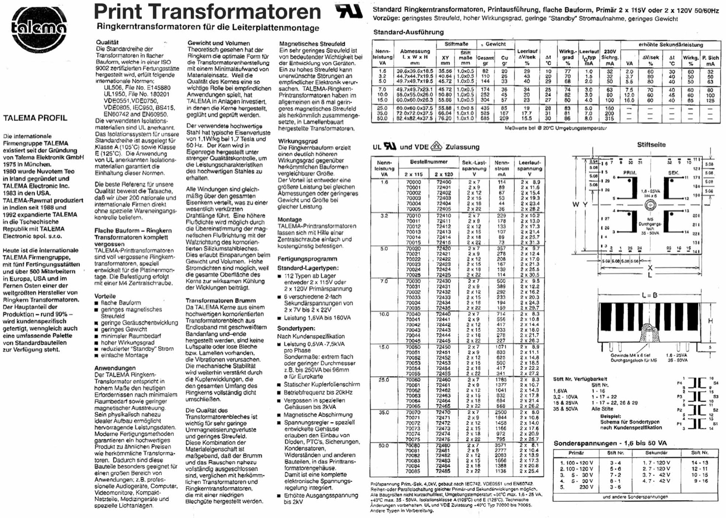
Whilst preparing a list of electronic parts i stumbled upon the “TALEMA print transformator type 70040 with 2 x 115V primary and 2 x 7V secondary”
Although i got the datasheet from “Reichelt Electronic”, unfortunately it is not clearly to see for me how the primary and secondary circuits internally are switched - could you please send a wiring diagram or explain this ?!?
Looking at the TALEMAs product description (attachment), on the primary / input side there are black points / marks beneath pin 6 & pin 4, on the secondary side there are two black points at pin 11 & pin 13 - what exactly do they mean ?!? I guess it has something to do with how the different circuits of the primary / secondary stage internally are switched.
There are two pairs of primary 115V inputs, from my understanding i had to connect the both inner ones while putting 220 / GND at the two outer pins to add both primary circuits “in line” and not “parallel” to archive the 220V.
Assuming this would be correct, how did you utilize the two secondary circuits ?!? Are you suppling 7 volts to the rectifier diodes or (assusming the same as on input / primary side) are you adding both circuits to archive an output of 14 volts ?!?
The stepdown/stepup converter i´ve choosen is the “DEOK DC4,5-30V auf 0,8-30V Buck Converter” from @mazon…
As one secondary output line of 7 volts imho is quite enough to supply the DEOK, Pi & HiFiBerry, i´m honestly asking you about the connection pins of the TALEMA 70040: Would it be correct to shorten pin 5 & 4 on the primary side and use pin 6 & 3 for the 220 volts input ?!? And, if so, would it be enough / ok to only use one secondary output of 7 volts and leave the other one unconnected ?!? This is the main question for me, as i cannot see (or understand…) anywhere in the TALEMA diagrams how the transformers primary and secondary circuits internally are connected amongst.
Thanks in advance - not for answering only - but for showing up this wonderful project !!!
Keep up the good work & don´t let the soldering iron become cold
Kind regards,
Huarez
Hello Huarez,
first, please be careful; you work with 230V AC. If you don’t have any experience with this, you should ask someone who know to work with.
The black mark is the direction of the winding from the copper. I had this transformer available and so I used it. You can also take a 6V 10VA or bigger (like Block VC 10/1/6)
Yes at the input (230V) you use 3-6 and make a jumper over 4/5.
For more power in the output you use both in a parallel connection. 11/13 - 12/14.
The DEOK DC4,5-30V auf 0,8-30V Buck Converter is not an ideal choice I think, because it is a switching module. If you take this, you can use any switching power supply.
LG Gerry
Gerry said: The DEOK DC4,5-30V auf 0,8-30V Buck Converter is not an ideal choice
He’s right! The problem you’ll have is that the convertor is a switched-mode device and will introduce ultrasonic ripple on to the supply lines. This is certain to heterodyne with the DAC clock, and will probably produce audible whistles that you won’t be able to get rid of!
If you use the transformer that Gerry suggested, you can use two bridge rectifiers and smoothing capacitors to give two isolated ~9V DC supplies. Use 2200µF 25V electrolytic capacitors (don’t bother with “audio grade” ones - they’re just a rip-off for the gullible). Use 7805 linear voltage regulators for your two 5V 1A supplies. Be certain to connect 100n ceramic capacitors from each leg of each 7805 to ground (ie: input to ground and output to ground). These are best soldered to the pins of the ICs so that they’re as close as possible to the chips. The 7805s can be bolted straight to the case for heatsinking, and this will give a common 0V rail, but be certain that the tabs make good thermal and electrical contact. Use 220µF 25V electrolytics from the output of each 7805 to ground - you’ll have two completely silent 5V 1A supplies - one for the Pi and the other for the DAC.
If anyone needs a diagram or layout, ask here, and I’ll draw something up for you all. :ugeek:
…albeit my reply comes a little late - thank you both very much for the excellent declaration of the details !!!
Following your advice i did not use the DEOK - thus preventing lots of “peaks” within the signals Even if it is (…for shure…) a little bit oversized for the project, at least another “ready-pre-build” voltage regulator from “audiophonics” ( Module d’ Alimentation linéaire régulé Double DC LT1083 20V 7.5A ) found its way into the case.
I decided to use this one because of its separated dual in/outputs, which ideally fits to the output of the torodial print transformer. All now perfectly fitted into a “MS-Tech CI-70” case, while using one output of the regulator for powering the Raspberry / HiFiBerry, while the other output exclusively is used to power the both case integrated (…and the raspi´s internally).
This had been done by connecting the second 5v output to the USB +/- 5V downside the Raspberry PCB, while the four datalines of both USB (white+green & blue/yellow) are connected to the USB pcb within the MS-Tech case
Still missing is the infrared connection, which will be added next days. For this i will utilize one of the 3,5mm jacks on front of the case - if everything is well prepared i also upload a photo here…
Again, thank you very much for the outstanding hints & declaration !!!
Kindest ragards,
Huarez
Hello mictester,
could you please post the diagram of the rectifier you suggested ?!? I´m asking this because right now i´m thinking of building another Volumio thing, but with much smaller dimensions - therefore it would be ideal to put the rectifying part directly onto the transformators pcb…
Thanks in advance, kindest regards !
Huarez
As promised, here’s the schematic of the dual 5V 1A supply for the Pi and the DAC:
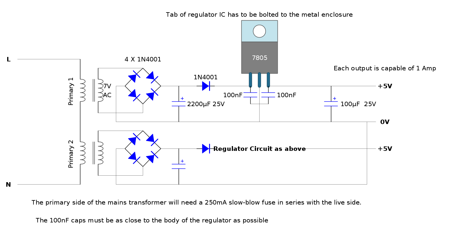
Remember - the primary side is LIVE - if you’re not confident about working with mains voltages, get the advice of someone who is!
Hi mictester,
thank you very much indeed for the picture !!
A very neat, small, and lightweight solution for the next Volumio project - this comes in very handy
Nevertheless, just one question about the 7805: Is is obligatory this must be the “CZ” type with fixed 5 volts output, right ?!?
Greetings !
Hello to you all,
I could use some advice:
I was thinking of using a single power supply for My RPI + HDD, using a power supply like this
ebay.com/itm/350787796287?_t … EBIDX%3AIT
What do you advise me to do a step-down voltage from 12v to 5v to power RPI and the HDD
this one:
ebay.com/itm/140832358304?_t … EBIDX%3AIT
or this:
ebay.com/itm/151129367602?_t … EBIDX%3AIT
it is advisable to use a power supply 12V / 5A or rather one 5V 4A
Thank you in advance!
Hi,
Get a 5V power supply if you don’t need 12V in your setup.
This is what I am using for my Pi 2, it is working OK. Don’t take the second one you listed, it has a linear regulator and the efficiency is poor.
thanks for the quick response Stephane!
another small question:
if I use a power supply of 5V / 4A I always have to use a step-down? (the first one)? , Always to avoid burning the hdd or the RPI?
or I can connect directly with all the power?