There is probably a way to set the bus speed.
yeah need to look into it.
So far not able to find anything to modify the bus speed.
In the meantime looked for a way to get this sucker dynamically found, as dmesg doesn’t reveal any i2c for this module.
So fell back to Adrii suggestion:
volumio@volumio-dev:~$ sudo i2cdetect -l
i2c-1   i2c             CP2112 SMBus Bridge on hidraw0          I2C adapter
volumio@volumio-dev:~$ udevadm info /dev/i2c-1
E: DEVPATH=/devices/pci0000:00/0000:00:14.0/usb3/3-13/3-13:1.0/0003:10C4:EA90.0001/i2c-1/i2c-dev/i2c-1
sudo nano /etc/udev/rules.d/96-cp2112.rules
SUBSYSTEM=="i2c-dev",  DEVPATH=="/devices/pci0000:00/0000:00:14.0/usb3/3-13/3-13:1.0/0003:10C4:EA90.0001/i2c-1/i2c-dev/i2c-1*" SYMLINK+="i2c-99"
sudo -u volumio /usr/local/bin/mpd_oled -b 32 -g 1 -P s -o SSD1306,128X64,I2C,bus_number=99 -f 20
driver: my-hid-mcp2112-1.0.0.0.zip (20.6 KB)
Fun fact:
Now you can have 2 displays running MPD_OLED
I can’t see anything either (apart from a 100 web pages saying the clock speed is configurable!) and it doesn’t look like the module accepts any parameters that could set the speed.
It is not something I know anything about, but Inside the driver there is code reading the current clock speed and then setting it the same, but the “report” that contains this value is a locally declared struct, so I am not sure how anything outside the module would set it. In which case you may be able to hardcode a clock speed of 400 kHz if you edit “hid-mcp2112.c” and find the line where config.retry_time is set and add a line underneath to set the clock_speed (find the first line below and add the second line)
   ...
   config.retry_time = cpu_to_be16(1);
   config.clock_speed = cpu_to_be32(0x61A80);
   ...
Documentaion: Section 5.6 of
https://www.silabs.com/documents/public/application-notes/an495-cp2112-interface-specification.pdf
Do what you need to do to get the module rebuilt and reinstalled after the change Kernel Korner - Exploring Dynamic Kernel Module Support (DKMS) | Linux Journal and, be ready with the fire extinguisher when you plug the board back in!
Adrian.
Ran:
sudo dkms uninstall -m my-hid-mcp2112 -v 1.0.0.0
sudo dkms remove -m my-hid-mcp2112 -v 1.0.0.0 --all
sudo rm -rf /usr/src/my-hid-mcp2112-1.0.0.0
sudo rm -rf /var/lib/dkms/my-hid-mcp2112-1.0.0.0
tested with:
config.clock_speed = cpu_to_be32(0x186A0); //100kHz
config.clock_speed = cpu_to_be32(0x61A80); //400kHz
config.clock_speed = cpu_to_be32(0x927C0); //600kHz
sudo cp -r /home/volumio/my-hid-mcp2112-1.0.0.0 /usr/src/my-hid-mcp2112-1.0.0.0
sudo dkms add -m my-hid-mcp2112 -v 1.0.0.0
sudo dkms install -m my-hid-mcp2112 -v 1.0.0.0
sudo reboot
testing:
mpd_oled -b 32 -g 1 -P s -o SSD1306,128X64,I2C,bus_number=2 -f 50
Still the response is lagging. looking at the response on the screen, without adding the line the Freq is already at 400kHz. When the bus was set to 100kHz the performance was even more dramatic.
Seems the CP2112 is not an option for CAVA. See movie speed set at 600kHz.
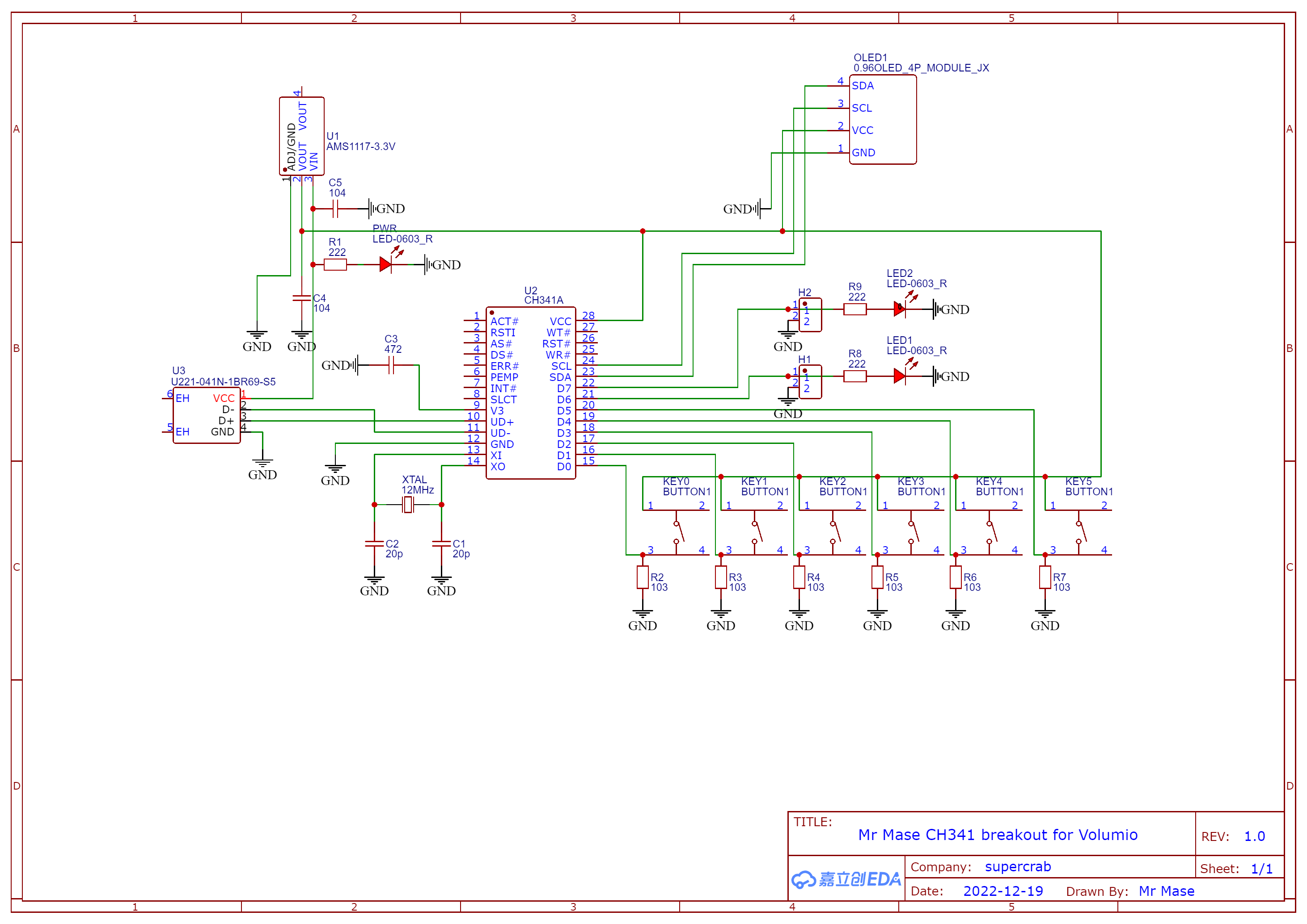
I’ll stick with the CH341A, as that one is working flawless.
CP2112.ZIP (8.4 MB)
That is a shame, as I preferred the format of this board over the others. Anyway, thanks for testing it!
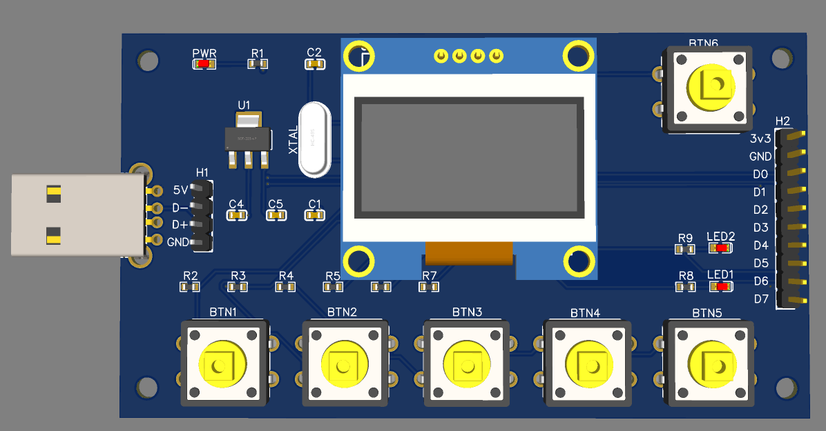
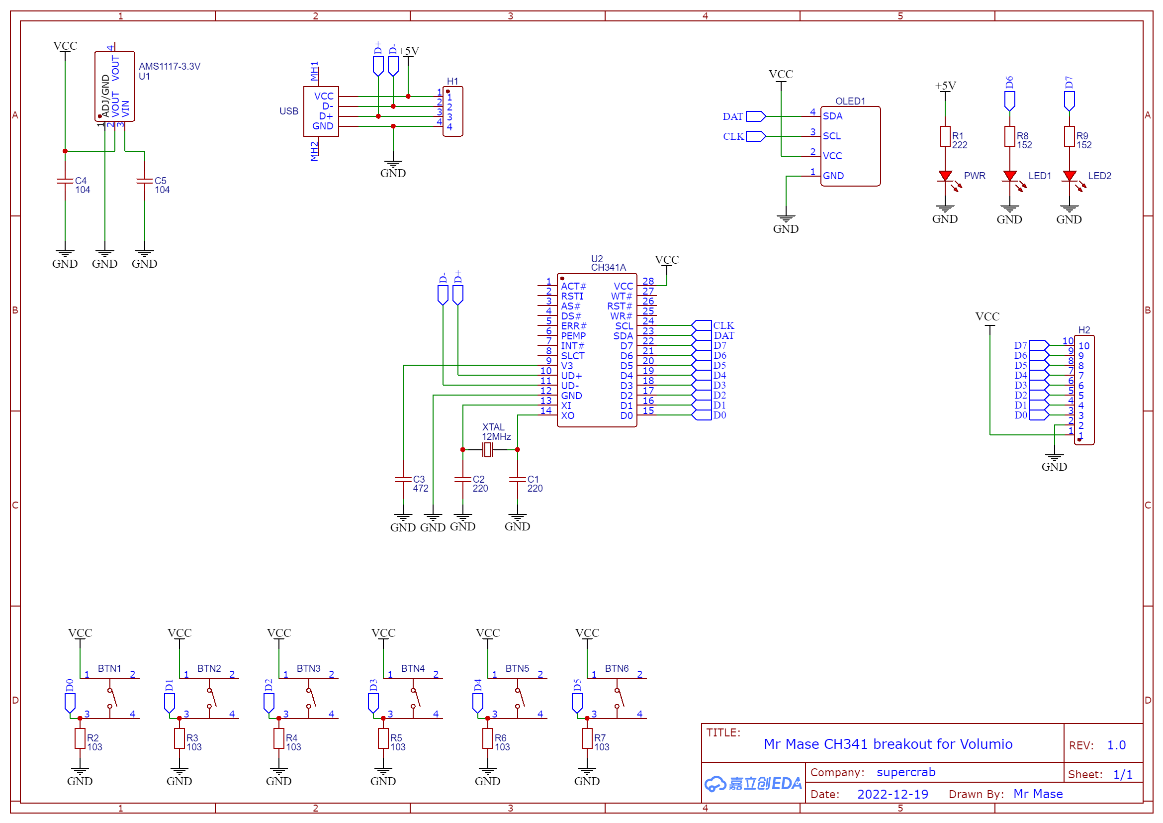
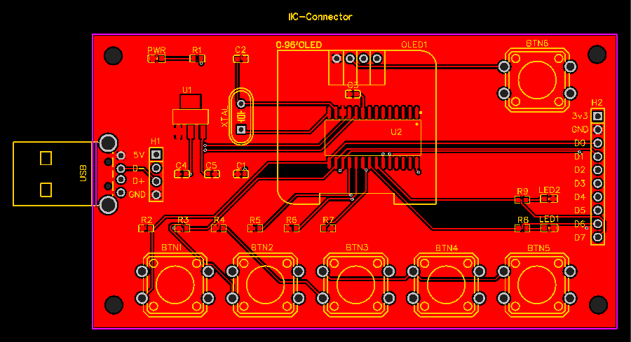
what if I design a PCB with CH341A, USB connector and 1.3" OLED display, that could nicely fit on a front USB port?
It should not take too much of my spare time, but of course no ETA for this side project
like the idea, but not sure how that would fit, as your depending on the location of the USB.
On top what will you make available, only SDA, SCL, VCC and GND, or including GPIO?
Currently I just took a std print and a flatcable, going to the back. So I could keep it small.
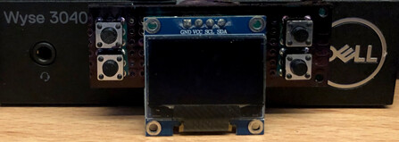
Added 4 buttons to select the display lay-out (Via GPIO)
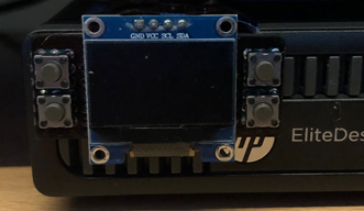
On the Dell it’s a nit fit.
OK it’s more complex than I thought, but the offer is still there.
If you give me some guidelines I can come up with a proposal
Funny guy 
Just a summary:
Depending if we’re including GPIO and i2c.
Connectios: SDA, SDL, VCC, GND, Do, D1, D2 D3, D4, D5, D6, D7 D8
Stick with 3,3V that removes 6 jumpers
Only 12c/SPI removes 3 jumpers.
That mens a redesign could fit on the same size as the 096" OLED
If only a OLED:
4 pins for SDA. SDL, VCC and GND.
Only 3.3V (removes 6 jumpers)
Only spi/i2c (removes 3 jumpers)
To be honest I have no clue if there is gonna be a need for it, looking at the amount of replies in this topic.
I would go for option one, and add a few buttons to it. I use it to select my display layout, but I could also imagine a PREV, PLAY , NEXT button and a IR receiver.
But with buttons, there is gonna be a lot of friction on the USB port…
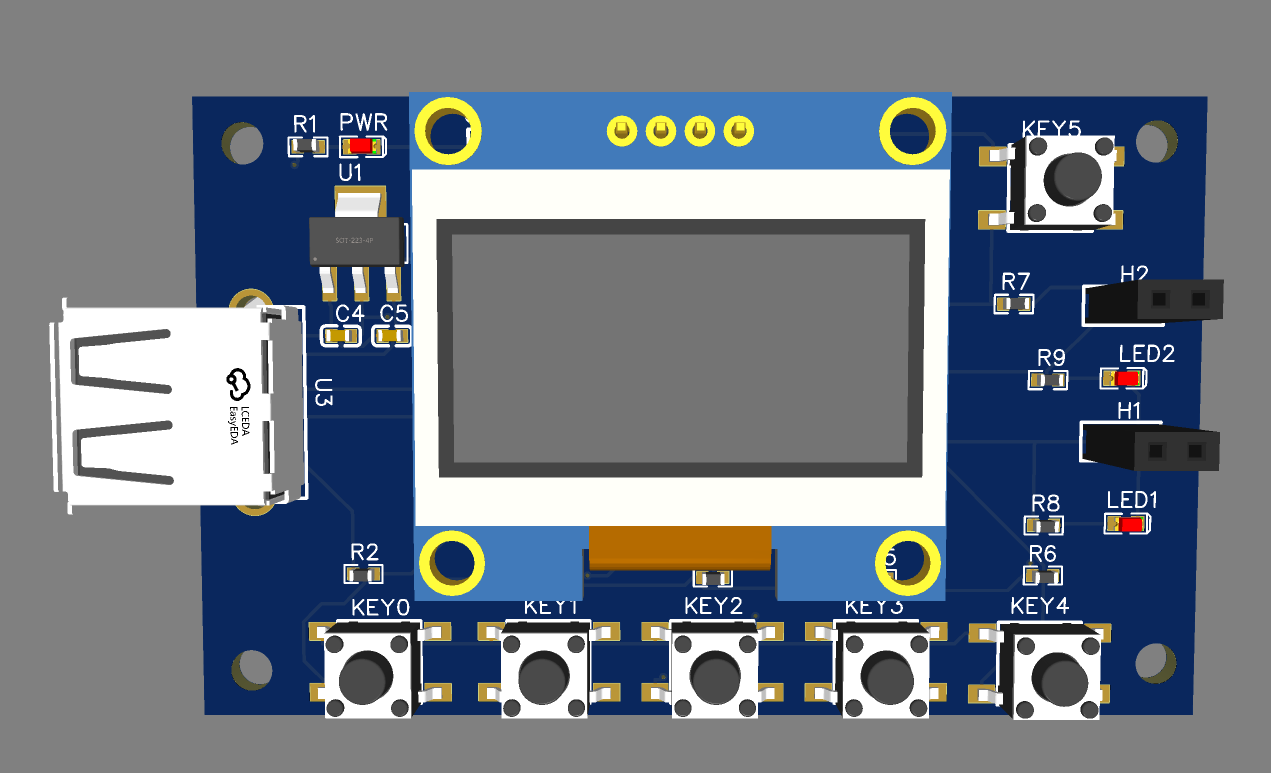
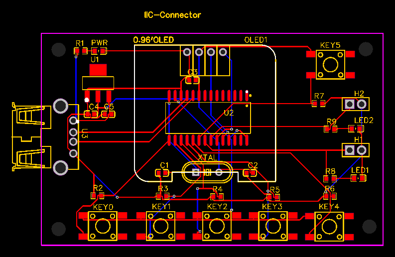
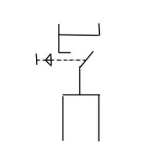
@wheaten @Darmur I did this in my lunchtime earlier today. It should work but I don’t know 100% for sure…
3 Likes
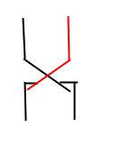
Looking good, Only be careful with the button selection. I have two different one, but both connect in a X-shape.
Cool way to spend a lunchtime. It looks like something you have been working on for months!
@Adrii it really did take about 30 mins using https://easyeda.com/ you can press a button and get the PCBs made for about £5
@Wheaten so is that 4 terminals but none of them are commoned so that’s actually 2 switches right?
Forget my fuzzy talking. (Depends on how the switch is in front of you when you measure it…  )
)
So both switches are like this, so you’re drawing is correct.
You just need to make sure you solder it in the right position.
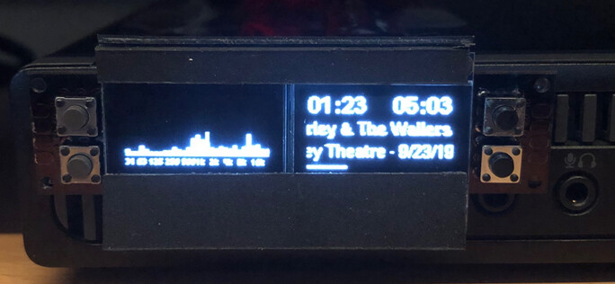
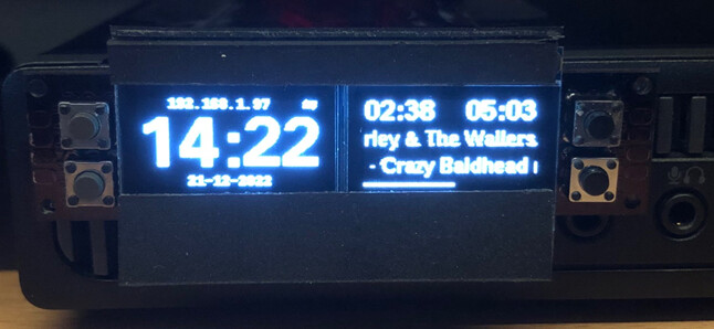
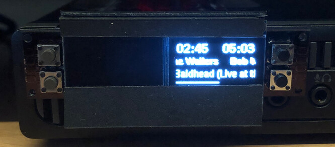
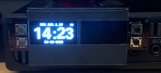
Since the CP2112 is to slow for cava, used it to display track info.
But even, just displaying seconds, the CP2112 is lagging.
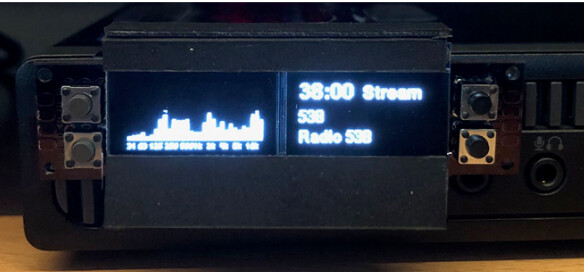

Ooh! Look at that!  @Wheaten
1 Like
He’s getting a taste for it, it’s looking better by each attempt.
Some thoughts:
- With the pins on the front, it’s becomes challenging to build in any case. So prob. this should be delivered as part, which can solder on if needed. (on the front or back). Even if you don’t build it in, with my fat fingers I will prob. rip connections everytime I press a button.
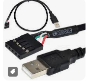
- Same for the USB connector. If you want to connect it, you’ll need an extension cable which becomes a big thing on the left. Most likely it’s preferable to use hooked pins, so you can connect it to the front or back, using:
- some prints tracks are behind the connection holes of the OLED. Which makes the OLED connection fragile as it’s only holding in place by the 4-pin connection. I would suggest that we can mount spacers.
1 Like