Before I explain, I’ll just name Vin =the voltage provided by the power supply. In my case I have a 12Vdc power supply, so Vin = 12Vdc.
The switch has to be a latched switch.
Details about the connector of the X400 are here: https://raspberrypiwiki.com/X400_V3.0
The issue in X400 documentation I mentioned above is on the power switch connector. The pin number 3, instead of being a ground, is actually Vin. Probably the switch simply cuts the line between the jack and the power converter of the board.
So here is how the documentation tells you to wire your switch :
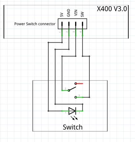
What we want to do is to connect pins 3 and 4 of the connector until the raspberry has shut down.
To do that, i use a relay powered by the Rpi and controlled by a GPIO that I will name «GPIO B». The GPIO will stay at 3,3V until the raspberry is down, and then go to ground. When that happens, the relay opens, and removes power from the X400 board.
Example of a relay board that can be used: https://www.amazon.com/HiLetgo-Channel-optocoupler-Support-Trigger/dp/B00LW15A4W/
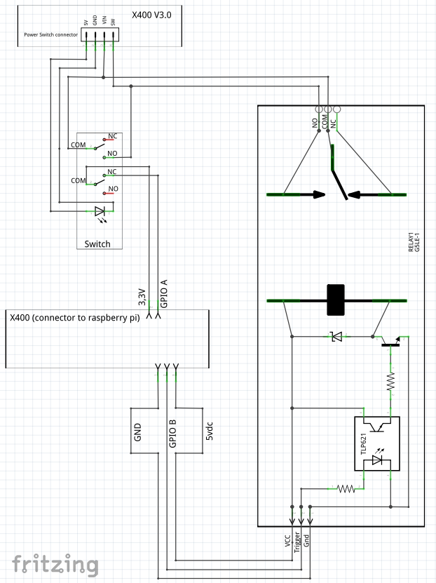
If you only do that, the switch is shorted as soon as the Rpi has started. Any action on the switch has therefore no effect. To use the switch as a trigger for shutting down the Rpi, you need another connection. For that purpose it is much better to use a switch with 2 poles (DPDT). In case you don’t have a DPDT switch, like me, check below for the alternative solution. The second pole connects a GPIO to 3,3V when the switch is in OFF position. That GPIO, that I will name GPIO A, will be configured as an interrupt that triggers the shut down of the Pi.
GPIOA and GPIOB can be any GPIO available on the connector, except for GPIO18 which is already used by the X400 board. I recommend the use of GPIOs 17, 22, 23, 24 or 27 for GPIO A because they have a default pull down, which is what we need here.
The wiring looks like that :
Configuration of the RPi
via SSH, edit /boot/userconfig.txt and add the following lines :
gpio=7=ip,pd
gpio=8=op,dh
dtoverlay=gpio-poweroff,gpiopin=8,active_low=y
the first line is for GPIO A (in that case GPIO A is GPIO 7). It sets the gpio as an input with a pull down. This line is not necessary for GPIOs 9-27.
the second line is for GPIO B (in that case GPIO B is GPIO 8). it sets the gpio as an output in a high state.
The third line sets the GPIO B so that it will go to ground once the Rpi is off.
Reboot.
Install the plugin GPIO-buttons, and set the shutdown gpio to one you chose for GPIO A.
Alternative Solution using a single pole switch (NOT RECOMMENDED)
In case you don’t have a DPDT switch, which can be hard to find if you look for one round with LED and pictogram, there is an alternative. However be extra careful when using it. The GPIOs only support input voltage between approximately 1,8V to 3,3V . Double check your calculations, your wiring, your assembly, because if anything above 3,3V is applied to the GPIO, it will destroy it.
Here we use the “Normally Close” pin of the switch that is set to Vin when the switch is turned off.
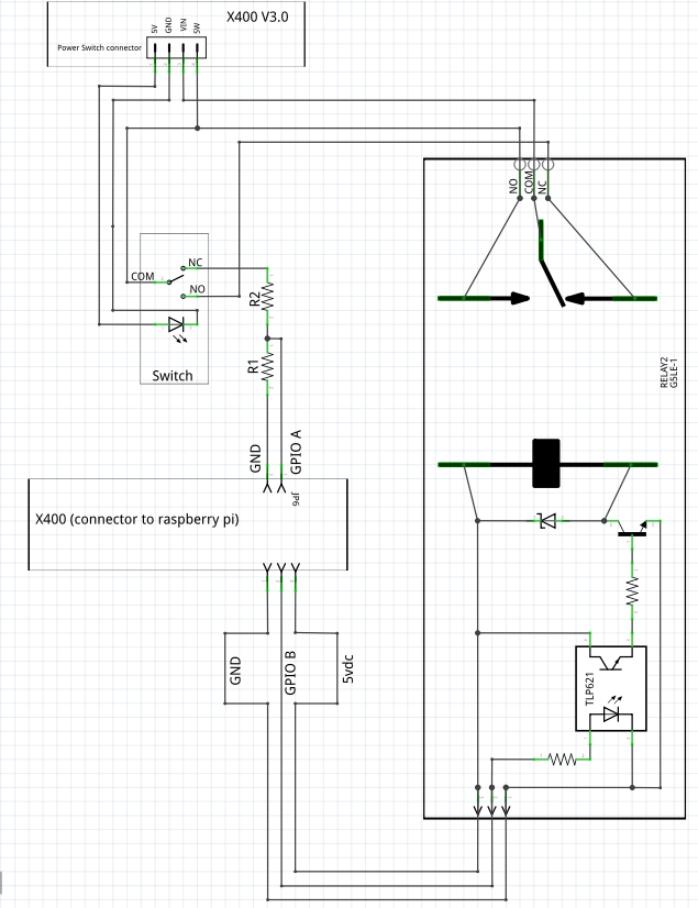
The wiring looks like that:
The GPIOs read a high state between 1,8V and 3,3V. The lower threshold is not guarantee so it is better to be as close possible to 3,3V, without exceeding it.
To lower the voltage Vin to an acceptable voltage for the GPIO, I use a voltage divider. The voltage on the GPIO is equal to R1/(R1+R2) * Vin. So R1 / (R1+R2) should be between 1,8V /Vin and 3,3V /Vin.
In my case, Vin is 12V. I used 4 resistors of same value, 1 is R1 and the 3 other in serie are R2. R1/(R1+R2) = 1/4, so the Voltage on the gpio is 12/4 = 3V. That is sufficient to be detected by the Rpi.
Don’t use to low values resistors: R1+R2 should not fall under 1000ohms, else you might burn the board. Don’t use too high value resistors either or the GPIO will not detect the voltage (i’d say max 10kohms for R1+R2). I used 560ohms resistors for example, so in my case R1+R2 is 2000ohms.
The configuration is the same as explained above.
Good luck 
 )
)