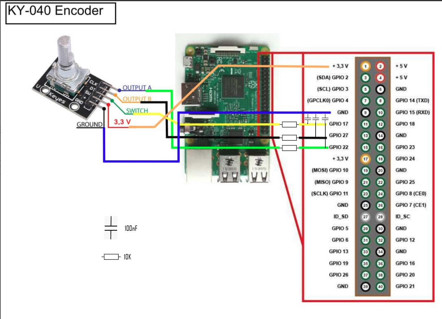
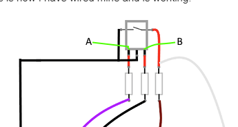
for your rotary which already has pull up resistors on the DT CLK and SW
extra resistors for protection and capacitors for stability wire like this.
for your rotary which already has pull up resistors on the DT CLK and SW
extra resistors for protection and capacitors for stability wire like this.
I’m going to put another rotary encoder, do I have to put the second one on other pins or can I put it on the ones where the first one is connected.
You can only share the 3.3V and ground. The other 3 needs to have their own GPIO.
make sure you connect them to GPIO’s that are configured as IN and are low.
wiringpi-latest.zip (51.1 KB)
unzip file to /home/volumio
run sudo dpkg -i wiringpi-latest.deb
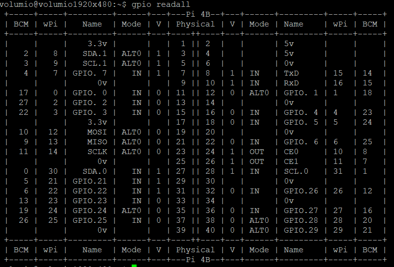
By executing gpio readall you can see how the GPIO are setup.
 +-----+-----+---------+------+---+---Pi 3B--+---+------+---------+-----+-----+
 | BCM | wPi |   Name  | Mode | V | Physical | V | Mode | Name    | wPi | BCM |
 +-----+-----+---------+------+---+----++----+---+------+---------+-----+-----+
 |     |     |    3.3v |      |   |  1 || 2  |   |      | 5v      |     |     |
 |   2 |   8 |   SDA.1 | ALT0 | 1 |  3 || 4  |   |      | 5v      |     |     |
 |   3 |   9 |   SCL.1 | ALT0 | 1 |  5 || 6  |   |      | 0v      |     |     |
 |   4 |   7 | GPIO. 7 |   IN | 1 |  7 || 8  | 0 | IN   | TxD     | 15  | 14  |
 |     |     |      0v |      |   |  9 || 10 | 1 | IN   | RxD     | 16  | 15  |
 |  17 |   0 | GPIO. 0 |  OUT | 0 | 11 || 12 | 0 | IN   | GPIO. 1 | 1   | 18  |
 |  27 |   2 | GPIO. 2 |   IN | 0 | 13 || 14 |   |      | 0v      |     |     |
 |  22 |   3 | GPIO. 3 |   IN | 0 | 15 || 16 | 0 | IN   | GPIO. 4 | 4   | 23  |
 |     |     |    3.3v |      |   | 17 || 18 | 0 | IN   | GPIO. 5 | 5   | 24  |
 |  10 |  12 |    MOSI |   IN | 0 | 19 || 20 |   |      | 0v      |     |     |
 |   9 |  13 |    MISO |   IN | 0 | 21 || 22 | 0 | IN   | GPIO. 6 | 6   | 25  |
 |  11 |  14 |    SCLK |   IN | 0 | 23 || 24 | 1 | IN   | CE0     | 10  | 8   |
 |     |     |      0v |      |   | 25 || 26 | 1 | IN   | CE1     | 11  | 7   |
 |   0 |  30 |   SDA.0 |   IN | 1 | 27 || 28 | 1 | IN   | SCL.0   | 31  | 1   |
 |   5 |  21 | GPIO.21 |   IN | 1 | 29 || 30 |   |      | 0v      |     |     |
 |   6 |  22 | GPIO.22 |   IN | 1 | 31 || 32 | 0 | IN   | GPIO.26 | 26  | 12  |
 |  13 |  23 | GPIO.23 |   IN | 0 | 33 || 34 |   |      | 0v      |     |     |
 |  19 |  24 | GPIO.24 |   IN | 0 | 35 || 36 | 0 | IN   | GPIO.27 | 27  | 16  |
 |  26 |  25 | GPIO.25 |   IN | 0 | 37 || 38 | 0 | IN   | GPIO.28 | 28  | 20  |
 |     |     |      0v |      |   | 39 || 40 | 0 | IN   | GPIO.29 | 29  | 21  |
 +-----+-----+---------+------+---+----++----+---+------+---------+-----+-----+
 | BCM | wPi |   Name  | Mode | V | Physical | V | Mode | Name    | wPi | BCM |
 +-----+-----+---------+------+---+---Pi 3B--+---+------+---------+-----+-----+
Depending on the GPIO pins used some pull up some pull down.
Picture of device on this link
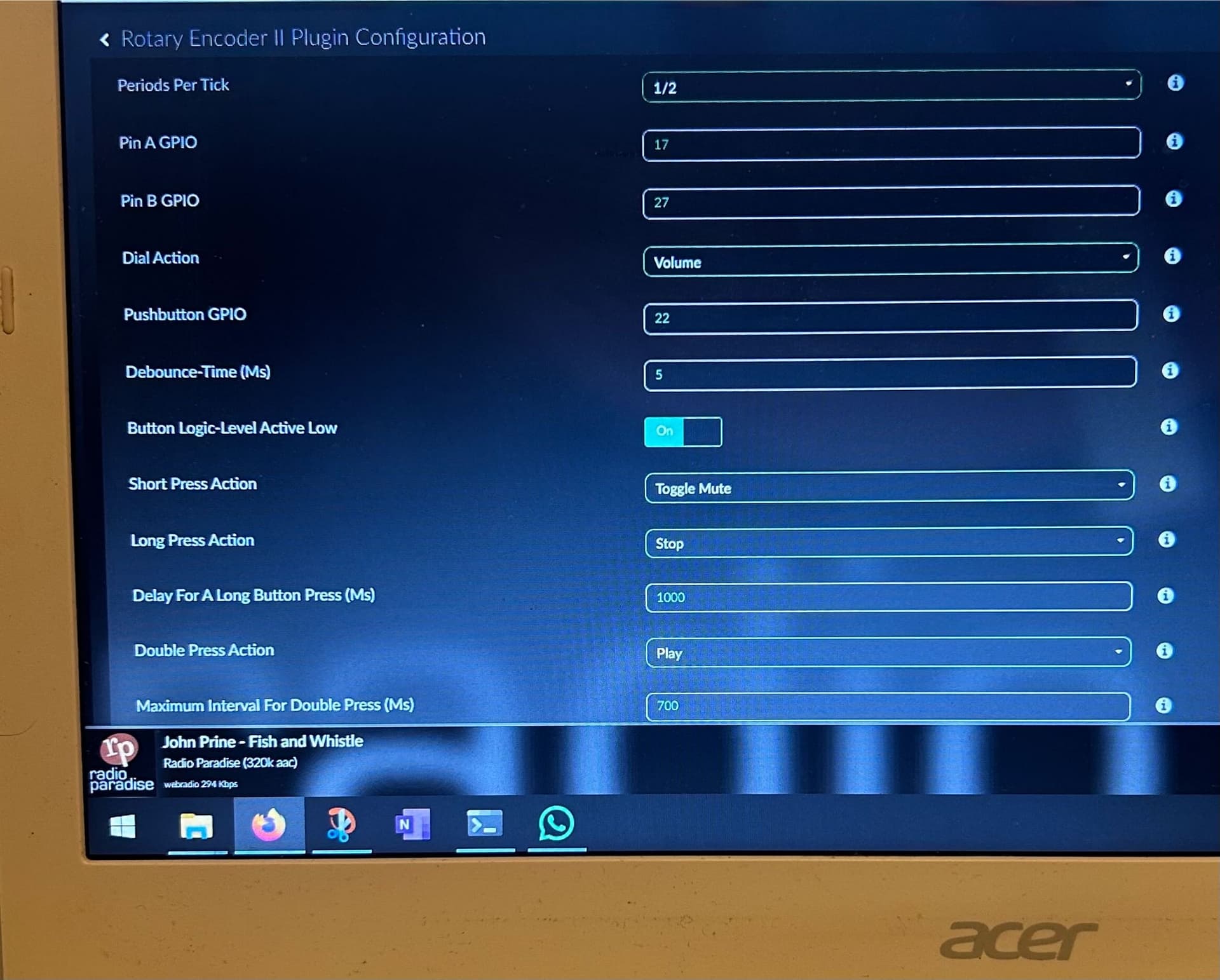
I also have problems with the configuration, I tried everything A on gpio 23, B on 24 and button on gpio 27, volume works but the button doesn’t. then A on gpio 5 and B on 6, volume works, button 27/22 or even 17, button doesn’t work. what do I have to do to make the button work? thanks for your patience
I’m sorry but I’m not very practical, I think I understood that you put resistors in front, then I saw so many cables attached in other gpios that I didn’t really understand why all these cables, and I don’t understand which one is clk, dt and sw. I’m sorry, can you be a little more precise, thanks
in practice I was able to make the button work, even in other configurations I tried. now the problem is that every time I restart, the button no longer works, only the volume works, the volume always works, the button doesn’t work after every restart. do you know what the solution could be? Thank you
Only look at the cables connected to the rotary switch.
You should have a little understanding on this matter. its called DYI for a purpose ![]()
Not every GPIO is default High or low. Some are toggling.
I’ll refresh a bit. If I have 2 encoders, do I connect both to the same pins? Do I just change the function in the settings?
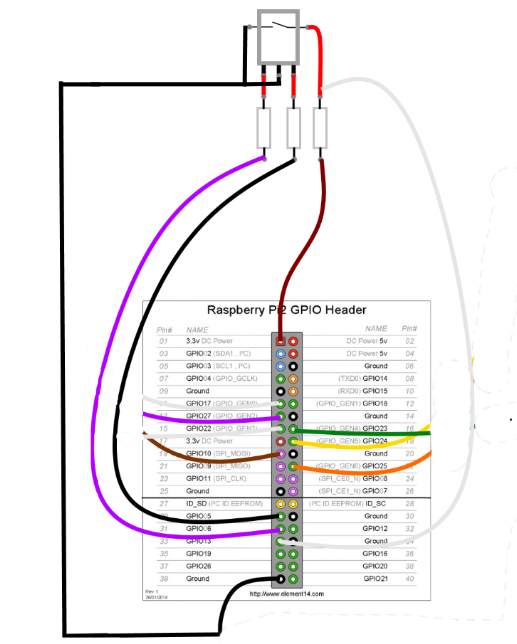
Only thing you can combine is VCC and ground. PINA,B and Push needs their own GPIO pin. How else would the OS distinguish which rotary your turning?
Volumio is smart,
it will definitely distinguish.
Thanks @Wheaten ![]()
![]()
not that smart. if you add a volume control on GPIO 5-6 and kip/next on GPIO5-6… Volumio has no clue.
did you connect SW to ground?
in my case between the GND and GPIO
I am pretty sure the complete drawing is given…
Only for me it doesn’t work on 5 and 6 (I tried before writing). On 23 and 24 it works (volume). SW doesn’t work.
Maybe later this week I have time to dig into this again. For me it worked on both rpi4 as rpi5.