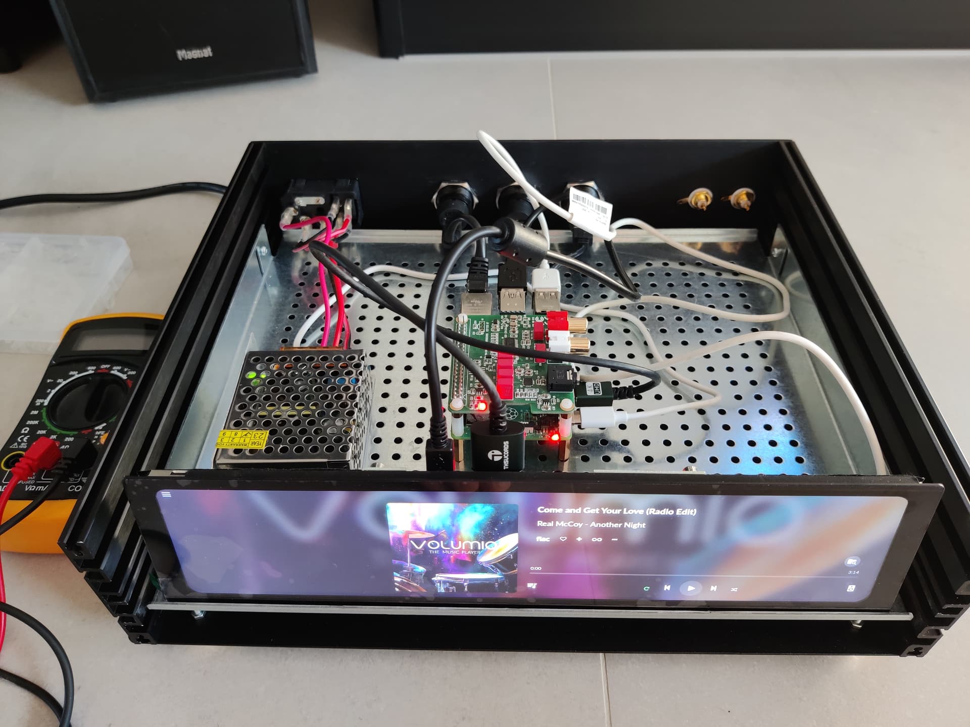
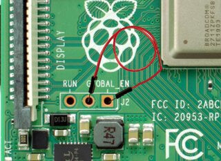
Hi I’m assembling my new dac project. I have a problem with the on and off button. I connected the button wires to Pins 5 and 6. It doesn’t work to turn it off, but when it turns on the Raspberry starts but the 11.9 Waveshare display lights up but the operating system doesn’t start. is there a guide to follow? what could be the problem?
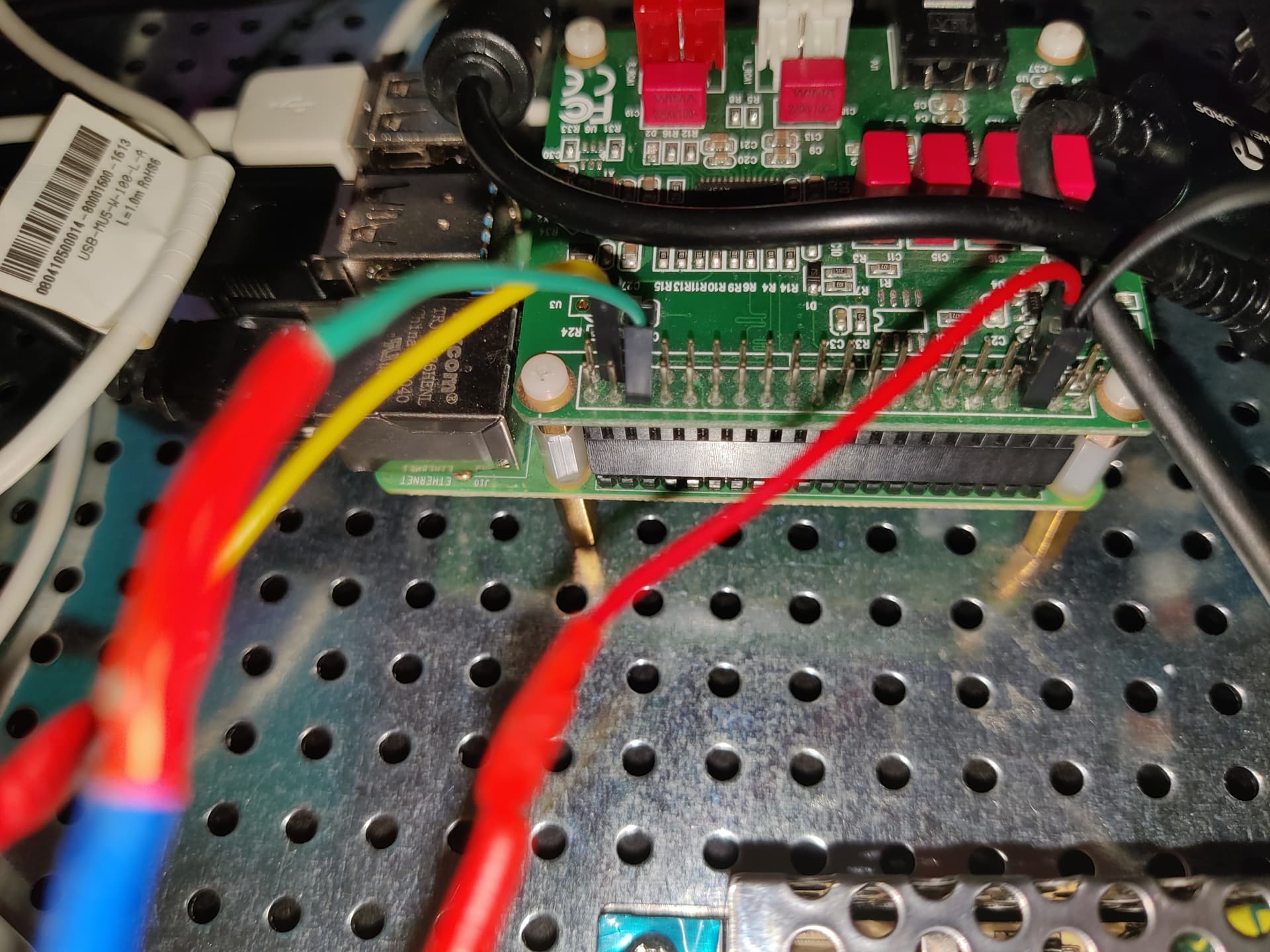
think you have a resource conflict, that both DAC and Switch fighting over the same pins.
I just nicked the power control board from an Argon1 case for my project (using an Allo DigiOne), which works like a charm.
could you explain how to solve it? Thank you
-
Well, open your browser and search for argon One.
The case is between 25-30 Euro, solder your on/off button over the one on the Argon One.
Install the script they provide
curl https://download.argon40.com/argon1.sh | bash
( This works with the LCD screen/Peppy_meter and you also have a Fan controller) -
You can also google on a power on/off script.
https://learn.sparkfun.com/tutorials/raspberryroller-pi-safe-reboot-and-shutdown-button
But be aware you can’t use a Python script if you want to use peppy_meter. (a Python while loop, breaks the screensaver routine. You can only use a bash script) -
You can also try this plugin:
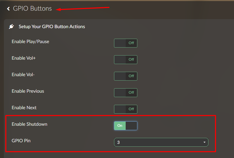
This working to turn off, but to press button for turn on freezing
Did you try to add a 2nd button on the reset pins?
Not now, i’m noob you explain?
Just add a button on these pins.
Then you have a shutdown button and a reset button that will reboot the rPi.
The best solution is to buy Argon One, there is V1 and V2 which should I get?
I had a V1 collecting dust, so I used that one.
There are others (boards, also cheaper) , just google on rpi4 power switch.
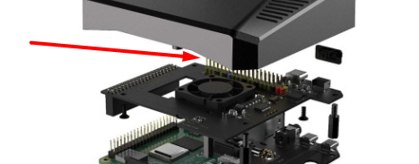
The advantage for me using the V1, is that it comes with and extended GPIO bracket, to which I could connect the HAT and has a FAN. (and it runs as a bash script, So peppy_meter is also working)
1 Like
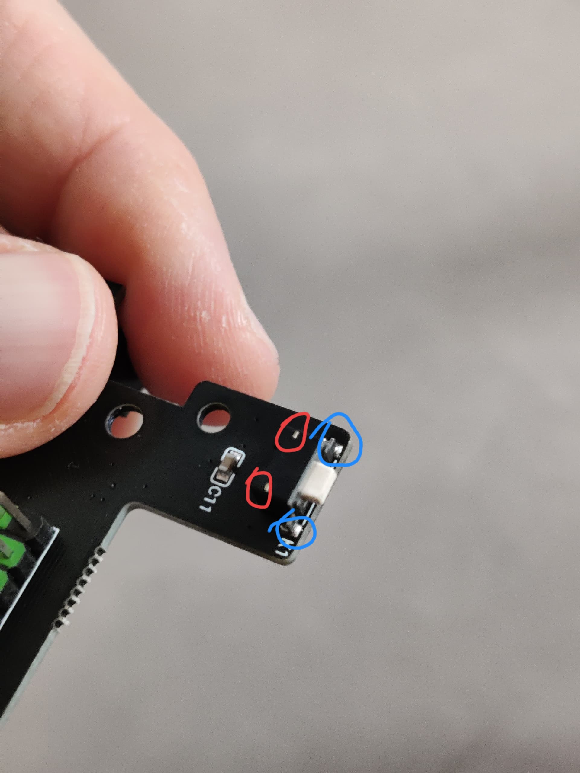
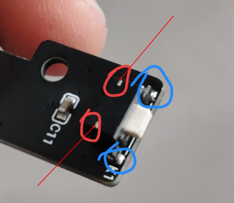
I soldered on the blue (circles) side
Thanks!!
You’re welcome.
Always like these kind of projects.
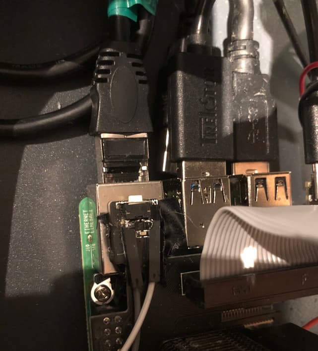
the original button been removed? I installed the plug-in and soldered the wires to the front but it doesn’t work
You shouldn’t have to remove it, just solder it over the existing switch. As it’s a multilayer PCB, you might have broke something.
That’s why I stated in the previous post:
You’ve installed the software, by executing from a ssh session?
curl https://download.argon40.com/argon1.sh | bash
You’re case switch is a “make” contact?
I installed the plugin correctly, the original button works, the one I soldered doesn’t work
let me open mine an I will share a screenshot, give a few minutes.
Since the original switch is still working, it means that the added switch is interrupted.
Check wires, soldering and the switch itself.
1 Like
thank you for your patience, I hope to repay you somehow!