Pi 3A+ + Volumio + Waveshare 2.8" SPI LCD - display is working, CST328 touch still WIP - help appreciated

Title: Pi 3A+ + Volumio + Waveshare 2.8" SPI LCD — display working, CST328 touch still WIP

A little while ago I posted here about the RAM requirements of Volumio 3 versus Volumio 4, particularly in relation to using a 512 MB Pi 3A+ with a local SPI display.

At the time I had Volumio 3 working on the 3A+ and displaying album art plus Artist, Album and Track metadata on a 320×240 SPI LCD.

I’ve continued working on that project, so I thought I’d share where I’ve got to — and ask for some help with the part I haven’t yet cracked.
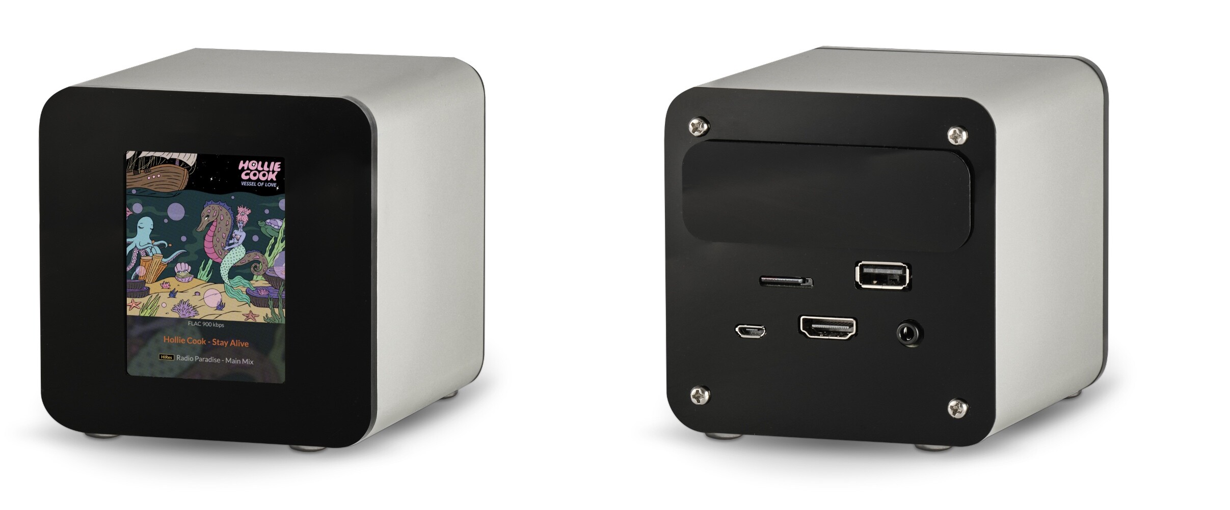
The display I’m using is the Waveshare 2.8" SPI LCD, SKU 27579.

It uses:

  • ST7789V LCD controller
  • CST328 capacitive touch controller
  • 320×240 IPS display

I’ve now got the ST7789V display side working reliably with Volumio 3, displaying album artwork and playback metadata.

I’ve had some help from colleagues along the way, who I’ve credited in the GitHub repository, and I’ve documented the working implementation there, including an automated installer and how-to:

The bit I haven’t solved yet is the CST328 touchscreen integration.

The LCD works. Touch is still WIP.

So rather than disappearing further down that particular rabbit hole on my own:

Has anyone here successfully integrated a CST328 capacitive touch controller with Volumio?

I’d be particularly interested in anyone using the same Waveshare SKU 27579, but experience with the CST328 on another display would also be very useful.

I’m also interested in whether anyone has built something similar using Volumio 4 / Bookworm, particularly with an SPI display and touch.

My previous concern was the 512 MB available on the Pi 3A+. If someone has already tried this combination on Volumio 4, successfully or unsuccessfully, I’d be interested to hear what happened.

If you’ve documented your implementation or have code available somewhere, please share it. I’d be very happy to compare notes.

The hardware in the photograph is part of a project I’ve been developing called PIXIS CB-1. It supports the Pi 3A+ and Zero 2 W, SPI and DSI displays and full- or half-size HATs.

I’m a big fan of Radio Paradise and it is my ‘go to’ radio station. I have this prototype on my desk so when I hear something I like but do not recognise I simply glance at the LCD and it gives me an instant visual - Album Cover Art, Artist and Track - no messing with my Phone or web browser - just a quick heads up and look.

For now, though, the problem I’m trying to crack is very specific:

Volumio + Waveshare SKU 27579 + CST328 touch.

Has anyone already been down this road? If so l’d love to hear about your experiences - be they positive or negative!

Peter
PIXISUK

1 Like

Hey @PIXISUK,

Good write-up, and thanks for crediting the people who helped you. Here is what I can contribute, split into what is established and what is not.

First, the kernel situation for the CST328, because it explains why this has been hard.

There is an in-tree driver, drivers/input/touchscreen/hynitron_cstxxx.c, present in the Raspberry Pi kernel tree on rpi-6.1.y, rpi-6.6.y and rpi-6.12.y. Two things about it matter:

  1. Its only devicetree match is “hynitron,cst340”. There is no cst328 compatible string. People who have got anywhere with a CST328 have bound it to the cst340 string.

  2. The probe does an identity check. It reads register 0xfcd1 and compares the top 16 bits against 0xcaca0000. On mismatch it logs “ic mismatch, chkcode is …” and returns -ENODEV. Whether CST328 silicon returns a matching code is not something I can state either way. I have not seen it verified, and I am not going to guess. A live read at that register on your hardware would answer it.

Second, and this is the part that probably matters most to you: the driver is not enabled in any Raspberry Pi defconfig. I checked bcm2709_defconfig, bcm2711_defconfig (arm and arm64), bcm2712_defconfig and bcmrpi_defconfig across the 6.1, 6.6 and 6.12 branches. CONFIG_TOUCHSCREEN_HYNITRON_CSTXXX does not appear in any of them. So the stock Raspberry Pi kernel ships no hynitron module, and neither Volumio 3 nor Volumio 4 will have one. That is an upstream build-config fact, not a Volumio decision.

There is also no hynitron or cst overlay in the kernel overlays directory. mipi-dbi-spi.dtbo is there, which is the ST7789 display path, but nothing for the touch controller. Any CST328 node has to be a hand-written dts compiled to a dtbo.

So to answer your actual question directly: no, I am not aware of anyone who has a working kernel-level CST328 input device on Volumio, on 3 or on 4. What I have seen reported on the Raspberry Pi forums is:

  • The Waveshare Python demo driving CST328 touch successfully over I2C on Pi 4 Bullseye and Pi 5 Bookworm, with no overlay loaded at all. Userspace polling, no kernel driver involved.
  • One contributor (aBUGSworstnightmare on the RPi forums) running a modified out-of-tree version of hynitron_cstxxx carried from 6.6.64 to 6.12.x, because in his case the in-tree register definitions did not match his CST328. He also published an overlay template worth starting from: node cst328@1a on i2c1, compatible “hynitron,cst340”, a pinctrl fragment setting the interrupt pin as input and the reset pin as output with pull-ups, irq-gpios, reset-gpios, touchscreen-size-x and touchscreen-size-y, plus dormant fragments for inverted-x, inverted-y and swapped-x-y.

Before I suggest anything further, I need to know which of two architectures you are actually building, because the answers do not overlap:

A. Your renderer is a userspace process pushing frames to the ST7789 over spidev, and you draw the album art and metadata yourself. If that is the case you do not need a kernel input driver at all. You poll the CST328 over I2C in the same process, map coordinates to your own hit regions, and call the Volumio API for play, pause, next. That path is already proven to work on Pi hardware. No module build, no overlay, no identity-check problem.

B. You want real input events into X, so that a browser or a toolkit sees touch. That needs a kernel input device, which means building the module out of tree, writing the overlay, and dealing with the cst340/cst328 identity gate.

If you are on A, this is a much smaller job than it currently looks. If you are on B, tell me and we can work through it properly.

Some Volumio-specific points while you are here, since the Waveshare wiki instructions assume Raspberry Pi OS and will mislead you:

  • There is no raspi-config on Volumio. Interface enablement is done in the boot config.

  • I2C is already enabled. volumioconfig.txt sets dtparam=i2c_arm=on for all boards, so bus 1 is live.

  • SPI is not enabled by default. Add this to /boot/userconfig.txt:

    dtparam=spi=on
    
  • /boot/userconfig.txt is the only file you should ever edit. config.txt and volumioconfig.txt are system-managed and will be overwritten on update.

  • Anything you place in /boot/overlays yourself is outside the update mechanism. Assume it will not survive an OTA and plan your installer accordingly.

For reference, the Waveshare wiring for this module in BCM numbering is MOSI 10, SCLK 11, LCD_CS 8, LCD_DC 25, LCD_RST 27, LCD_BL 18, TP_SDA 2, TP_SCL 3, TP_INT 4, TP_RST 17. Note that MISO is not brought out on either the 13-pin connector or the 18-pin FPC. Also worth noting the panel is 240(H) x 320(V) native, so whatever orientation you settle on is a rotation applied on top of that.

On your Volumio 4 question for the 3A+: the 512 MB figure is workable for a headless player. It is not workable once the Chromium kiosk is running, and that was the correction Dario Murgia made to my earlier post on minimum requirements. Since your project renders its own output rather than running the kiosk, the kiosk memory ceiling should not apply to you. That is my reading of your setup rather than something I have measured on your hardware, so treat it as such until you test it.

Kind Regards,

@nerd — many thanks. This is exceptionally helpful, and your A/B distinction has clarified something important for me.

I am definitely A — and having gone back through the touch development work I’ve already done, I’m actually rather further down that route than my original post suggested.

Given the 512 MB RAM limitation of the Pi 3A+ and Zero 2 W, I’m not using the Linux framebuffer, Chromium or X for the display. Your previous discussion on this forum with @Wheaten about the differences between Volumio 3 and Volumio 4 — and particularly the conclusion that a Chromium kiosk is not viable within 512 MB — helped inform that direction.

My Python application instead fetches the Volumio state and artwork and builds the complete 240×320 screen in userspace using Pillow — album art, Artist/Album/Track metadata and the rest of the UI. The resulting image is passed to the Waveshare-derived LCD_2inch8 ST7789V driver, which writes directly through spidev to /dev/spidev0.0 and hence to the LCD over SPI.

So the lightweight userspace display wasn’t simply an optimisation: it was the route that allowed me to retain the Pi 3A+ and Zero 2 W as viable 512 MB platforms while still providing a local graphical display.

The working Volumio 3 LCD implementation and installer are here:

The touch side has followed a rather less direct path.

I initially experimented with exposing the CST328 through uinput as a Linux virtual touch device. But as the work progressed, handling touch directly in userspace started to make much more sense for what I actually need.

Getting reliable touch capture wasn’t straightforward.

I went through several iterations which failed to capture real finger touches consistently. In particular, I initially made the wrong assumptions about the IRQ behaviour and about when valid coordinate data would actually be available.

I ended up writing a series of small test programs to investigate the problem in pieces — looking separately at IRQ timing, D005 readiness and X/Y stability.

What eventually worked reliably was:

  • treating IRQ as an event hint, rather than assuming it meant valid coordinate data was immediately available;
  • using D005 as the real touch/report-ready gate;
  • reading the coordinate packet from D000;
  • taking multiple coordinate samples and allowing a sensible amount of X/Y drift for a real finger rather than requiring identical readings;
  • accepting a stable coordinate and mapping it into an application-specific screen zone; and
  • clearing D005 ready for the next touch.

That now gives me reliable touch detection across seven UI regions: four zones (A1–A4) covering the album-art area and three zones (B1–B3) across the lower metadata area.

The final userspace capture implementation is here:

The accompanying development notes are here:

Unfortunately I haven’t retained all the intermediate test scripts. They were working/debug files rather than something I thought I would need later, but the README records the development path and what I learned from them.

So your Architecture A recommendation independently confirms where I’ve ended up experimentally: the display and touch can both remain application-specific userspace functions.

The remaining job now looks considerably smaller than trying to turn the CST328 into a conventional Linux input device: add the necessary debounce/deduplication, decide what each of the seven zones should actually do, and connect those events to the appropriate Volumio API calls — initially things such as play/pause, next and previous.

Your explanation of the kernel-driver situation is particularly useful because it tells me that, for this application, I probably don’t need to solve that problem at all.

Your Volumio 4 comments are equally interesting. The earlier discussion established that the Chromium kiosk is the problem on a 512 MB Pi, rather than 512 MB necessarily ruling out Volumio 4 as a headless player. Since this implementation doesn’t run the kiosk at all, it raises the possibility that the Pi 3A+ and Zero 2 W can remain useful platforms under Volumio 4.

As you rightly say, though, that last part still needs proving on the actual hardware. Testing this implementation on Volumio 4 with 512 MB is therefore an obvious next experiment.

Thanks also for the /boot/userconfig.txt and OTA warnings. I’ll check the installer against those as well.

If you have a chance to look at touch_capture_final.py and see anything in the userspace approach that you think I’ve misunderstood — or anything you would approach differently — I’d be very interested to hear it.

Otherwise, I think you’ve helped confirm the shortest route to getting the touch UI finished.

Many thanks,

Peter

Hey @PIXISUK,

Thanks for the detailed write-up, and for publishing the code. Architecture A is clearly the right call for what you are building, and the fact that you arrived there experimentally before I described it suggests the constraints were doing the deciding.

I have read touch_capture_final.py. Comments below, ordered by how much I think they matter. One is a concrete defect, the rest are hardening and portability.

  1. write_nbyte does not do what it looks like it does

This line:

bus.write_byte_data(CST328_ADDRESS, (reg >> 8) & 0xFF, ((reg & 0xFF) << 8) | (val & 0xFF))

For reg=0xD005, val=0 the third argument evaluates to 0x0500, which is 1280. In py-smbus (python3-smbus, from i2c-tools), SMBus_write_byte_data parses that argument as a C int and then casts it: i2c_smbus_write_byte_data(fd, (__u8)cmd, (__u8)val). The cast truncates silently. There is no exception.

So the bytes that actually reach the controller are 0xD0 0x00. The low address byte 0x05 and your value are both discarded. What you have written is not “clear D005”, it is “set the read pointer to 0xD000”.

Your read path is unaffected, because there both arguments already fit in a byte. read_nbyte(0xD005, 1) correctly emits 0xD0 0x05 and then reads.

Corrected helper:

def write_nbyte(reg, val):
    bus.write_i2c_block_data(CST328_ADDRESS, (reg >> 8) & 0xFF,
                             [reg & 0xFF, val & 0xFF])

That emits the three bytes 0xD0 0x05 0x00 as intended.

Working hypothesis, not a conclusion: because you only act on IRQ edges, the un-cleared status has not shown itself yet. The edge is doing the gating that the clear was supposed to do. I would expect this to become visible once you add hold or repeat behaviour, where you need to distinguish a fresh report from a stale one. Verify by reading D005 immediately after your clear and seeing whether it is actually zero.

  1. Upstream has a cheap validity check you are not using

The mainline driver drivers/input/touchscreen/hynitron_cstxxx.c reads the same block at 0xD000 and derives X and Y with exactly the arithmetic you use. Two things it does that you do not:

  • It reads 28 bytes and rejects the packet unless buf[6] == 0xAB and buf[0] != 0xAB. That is a one-comparison validity gate on every read.
  • It takes the touch count from buf[5], which is register 0xD005 and is therefore already inside the packet you just read.

You are issuing a second I2C transaction to fetch D005 again inside read_xy_packet. That is not just redundant, it means your coordinate data and your point count are sampled at different instants, and coord_close requires a[2] == b[2]. A point count that flickers will restart your stability window for no good reason.

Suggested change:

def read_xy_packet():
    buf = read_nbyte(0xD000, 28)
    if buf[6] != 0xAB or buf[0] == 0xAB:
        return None
    x = ((buf[1] << 4) + ((buf[3] & 0xF0) >> 4))
    y = ((buf[2] << 4) + (buf[3] & 0x0F))
    points = buf[5] & 0x0F
    return x, y, points

read_stable_xy then needs to skip a None sample rather than append it. My expectation, stated as a hypothesis, is that the check byte lets you shorten your stability window, because invalid packets get rejected outright rather than being averaged against.

Also worth knowing: upstream signals end-of-read by writing 0xAB to 0xD000, not by zeroing D005. With the corrected helper that is write_nbyte(0xD000, 0xAB). Worth testing both once the helper actually transmits.

  1. Reset pulse is short

You hold TP_RST low for 1 ms. Upstream holds reset asserted for 20 ms and then allows up to 60 ms settling before touching the bus. I have no CST328 datasheet, so I cannot tell you 1 ms is wrong. I can tell you it is well below what the kernel driver considers necessary for this family, and that a marginal reset tends to show up as intermittent failure after power-on rather than as a clean fault. Cheap to lengthen.

  1. Things that matter once this becomes a service rather than a test script
  • No exception handling on the I2C calls. A single OSError from a bus glitch terminates the process. Wrap the read helpers and continue.
  • Logging volume. You log every IRQ sample, every D005 poll and every XY sample. On Volumio /var/log is tmpfs, which means RAM, on a board where RAM is the whole reason this project exists. Put the per-sample logging behind a debug flag and log only accepted events by default.
  • The 1 ms poll loop keeps the interpreter awake continuously. GPIO.add_event_detect or GPIO.wait_for_edge pushes the wait into the kernel and idles the process. On a 512 MB single-core-class target that is worth measuring rather than assuming, but it is the obvious candidate.
  • You trigger on the rising edge of TP_INT, so your action fires when the finger lifts, not when it lands. That is a legitimate choice for a button UI. Just make sure it is a choice.
  1. Coordinate orientation

zone_for_xy assumes the panel-native portrait frame, 240 wide and 320 tall. If your Pillow renderer composes in that same frame, nothing to do. If it composes landscape and the LCD driver rotates on the way out, the touch coordinates arrive unrotated and you need the inverse transform before the zone lookup. I cannot tell which from the capture script alone. What does the renderer do?

  1. Volumio 4 items for the installer

Since you are planning to test this on V4, three things will bite that did not exist on Buster:

  • Bookworm marks the system Python as externally managed (PEP 668). Plain pip3 install will refuse. Use distribution packages where they exist (python3-smbus, python3-pil, python3-numpy, python3-rpi.gpio) or a venv.
  • SPI is not enabled by default on Volumio. There is no raspi-config. Add dtparam=spi=on to /boot/userconfig.txt. I2C is already on, volumioconfig.txt sets dtparam=i2c_arm=on for all boards.
  • RPi.GPIO is deprecated on Bookworm and does not work on Pi 5 at all. It is fine on 3A+ and Zero 2 W, which are your targets, but if you ever want the same code to run on newer boards, gpiozero with the lgpio backend or python3-libgpiod is the forward path.

On the 512 MB question generally: your reasoning is sound, and since you never start the kiosk the ceiling that applies to a normal V4 install should not apply to you. That remains a prediction until you run it. When you do, please post what you measure rather than what you expect, and include a log link. That result would be genuinely useful to other people on 3A+ and Zero 2 W hardware.

Nice work on the capture pipeline. Treating IRQ as a hint rather than as data is the correct conclusion and it is not an obvious one.

Kind Regards,

That’s so helpful - many thanks. I guess by now you can tell I’m a 98% hardware and 2% software guy!

To answer your question on the renderer orientation - zone_for_xy assumes the panel-native portrait frame, 240 wide and 320 tall as you say, so the Pillow renderer composes in that same frame.

I’ll work my way through your suggestions and no doubt will finish up with code that works properly rather than just works on the bench! I’ll let you know how I get on.

FYI I found a CST328 Datasheet at https://www.buydisplay.com/download/ic/CST328_Datasheet.pdf

Happy to send you a kit of parts if you have the time/inclination to experiment. Just DM me a delivery address and I’ll pop one in the post. peteratpixisdotuk.

Thanks again for the support.

Peter

Hey @PIXISUK,

That datasheet is the missing piece. Thank you for finding it. It corrects one thing I told you, sharpens two others, and answers a question I left open in my first reply.

  1. Correction: my reset timing comment was wrong

I said your 1 ms reset pulse looked short, reasoning from the kernel driver’s 20 ms. The datasheet says otherwise.

Section 10.5, power on/reset:

  • TRST, reset pulse time, typical 0.1 ms
  • TPR, RST pin delayed pull-up time, typical 1 ms
  • TPOR, chip initialisation time after power-on, typical 200 ms
  • TRON, chip re-initialisation time after reset, typical 200 ms

Your 1 ms assertion is ten times the specified pulse. That part is fine and I was wrong to flag it.

The number that does need changing is the one after it. You wait 50 ms following release, against a specified re-initialisation time of 200 ms. That is a 4x shortfall, and it is the more likely candidate of the two for intermittent post-power-on behaviour.

def reset_touch():
    GPIO.output(TP_RST, 0)
    time.sleep(0.001)
    GPIO.output(TP_RST, 1)
    time.sleep(0.25)

Also from 10.5: RSTn has a built-in pull-up and RC filter and may be left floating externally. So GPIO.cleanup() releasing that pin on exit is harmless.

  1. Your X/Y arithmetic is confirmed correct, and there is a better validity gate available

Section 12 documents the normal-mode report exactly as you parse it:

  • 0xD000: high nibble is finger ID, low nibble is finger status, 0x06 means pressed
  • 0xD001: X_Position >> 4
  • 0xD002: Y_Position >> 4
  • 0xD003: high nibble X_Position & 0x0F, low nibble Y_Position & 0x0F
  • 0xD004: pressure
  • 0xD005: bit 7 (0x80) is the button flag, low bits are the finger count
  • 0xD006: fixed 0xAB
  • 0xD007 onward: fingers 2 to 5, five bytes each

So the 0xAB check I suggested is a documented fixed marker, not a heuristic, and buf[5] being the finger count is documented too, which confirms the second D005 read in read_xy_packet is redundant.

The better gate is one I missed first time round. The low nibble of buf[0] is a documented pressed/lifted status. Testing it directly is cheaper and more precise than inferring validity from coordinate stability:

def read_xy_packet():
    buf = read_nbyte(0xD000, 28)
    if buf[6] != 0xAB or buf[0] == 0xAB:
        return None
    if (buf[0] & 0x0F) != 0x06:
        return None
    x = ((buf[1] << 4) + ((buf[3] & 0xF0) >> 4))
    y = ((buf[2] << 4) + (buf[3] & 0x0F))
    points = buf[5] & 0x7F
    return x, y, points

Note the count mask is 0x7F, not 0x0F, because bit 7 is the button flag. With a maximum of five fingers your 0x0F never actually misreads, but 0x7F is what the field is.

My expectation, and it is an expectation rather than a result, is that with a documented pressed status and a documented check byte you can cut the stability sampling down considerably. Worth measuring rather than assuming.

  1. Important detail on the write helper I gave you

The datasheet issues mode commands as address-only two-byte writes. For example ENUM_MODE_NORMAL is “Write 0xD1 0x09”. That is the same shape as your existing read pointer set:

bus.write_byte_data(CST328_ADDRESS, 0xD1, 0x09)

Writing a value to a register is a three-byte transaction, address high, address low, then data. That is the write_i2c_block_data form I sent you.

These are not interchangeable. Use the two-byte form for commands and the three-byte form for register writes. If you feed a command through the three-byte helper you will send a spurious data byte.

Caveat worth stating plainly: the register appendix documents no write to 0xD005 and no end-of-read command at all. The kernel’s D0 00 AB sequence is not in this datasheet either. So both your original clear and my suggested alternative are undocumented behaviour. The corrected helper at least makes the write actually happen; what the chip does with it is something you will have to observe.

  1. The kernel driver question from my first reply now has an answer

I said I could not tell whether a CST328 would pass the mainline driver’s identity check. The datasheet settles it on paper.

Section 12 documents register 0xD1FC as holding firmware verification code 0xCACA, reachable after issuing the ENUM_MODE_DEBUG_INFO command “Write 0xD1 0x01”. Mapping the driver’s constants, which are little-endian byte sequences rather than register numbers as written:

  • 0x01d1 sends D1 01, the documented DEBUG_INFO command
  • 0xfcd1 sends D1 FC, register 0xD1FC
  • ic_chkcode 0xcaca0000 tests for the documented 0xCACA
  • 0x09d1 sends D1 09, the documented NORMAL mode command
  • 0x08d2 is register 0xD208, the documented firmware version register

The report format the driver parses is the same one documented here, byte for byte.

So the “hynitron,cst340” binding looks considerably more plausible for a CST328 than the one discouraging forum report I cited suggested. This is a paper comparison only. It does not prove the driver probes cleanly on real silicon, and it does not change the fact that the module is not enabled in any Raspberry Pi defconfig. It is irrelevant to what you are building. I am recording it because the next person searching for CST328 on a Pi will find that forum post and give up, and they should not.

  1. Two other things in there you may find useful
  • The default I2C address is documented as 0x34/0x35, which is the 8-bit pair for 7-bit 0x1A. Your constant is right. Note the address is customisable in firmware, so a clone module could differ.
  • Register 0xD1F8 reports the panel’s own X and Y resolution. You could read it rather than hardcoding, though for a fixed product that is a nicety.
  • Section 10.6 says IRQ asserts only when a valid touch needs reporting, and that the edge is configurable as rising or falling. Working hypothesis: your finding that IRQ is a hint rather than a data-ready signal may be a consequence of triggering on the release edge. Trying falling-edge detection and checking whether D005 is ready sooner would test that.

On the kit of parts, that is a generous offer and I would like to take you up on it. I will send you a PM.

Kind Regards,

Hi @nerd

Many thanks — and that background makes your offer to put it on the bench particularly valuable.

I’ll send you a complete working CB-1 unit with the Waveshare 2.8" SKU27579 display, together with a known-working Volumio 3 Internet Radio SD card. That will give you a working reference configuration before you start pulling things apart.

I’ll also include a short Quick Start covering the network setup, existing software/GitHub material and the known state of the touch work.

I do have a few specific things I’d be interested in seeing tested, but rather than give you a shopping list now I’ll keep it short and separate what would be useful specifically to PIXIS from the kernel/DT work you’re interested in doing yourself.

I’m particularly pleased that you’ll be able to test the mainline hynitron_cstxxx binding against real CST328 silicon. Whatever the result, having an actual measurement rather than another inference from the datasheet should be useful well beyond PIXIS. And a working Debian touch dtbo for the CST328 a real bonus for others who have struggled with this display.

I’ll let you know when the kit is on its way.

Many thanks again,

Peter

Hi @nerd

I’ll be posting the Volumio LCD player to you today.

I’ve configured it as a ready-to-run Volumio system so you shouldn’t need to install anything before testing. It is currently set up with:

  • Volumio 3.912
  • PIXIS Volumio-LCD v1.0.0
  • Waveshare 2.8" SPI LCD (240×320) with the Hynitron CST328 capacitive touch controller
  • LCD startup screen showing the hostname and IP address
  • Album art and metadata display during playback
  • Revised CST328 touch test code already installed
  • All required Python/I²C dependencies installed

I’ve tested the complete unit here, including reboot, Wi-Fi reconnection, Volumio playback, album art/metadata and the LCD backlight. I’ve also tested the revised CST328 code against the touchscreen.

When powered up It should broadcast it’s hotspot Volumio-CCB71 and display

Volumio LCD

Host: volumionerd

IP: 192.168.211.1

And once connected to the hotspot from there you can set your home network credentials.

Once you’ve got the unit connected to your network, the LCD should again show its hostname and new IP address on your home network.

If you open a browser at that IP address you should get the default Volumio screen. If you go to the installed plugin - Radio Paradise - and select the Flac main mix it should connect and start streaming and Album Art appear on the LCD. Audio should output to Headphone.

The touch code is deliberately not configured to start automatically. I wanted to keep it separate from the normal Volumio/LCD operation. It includes your suggested improvements.

When you’re ready to test the touchscreen, SSH into the unit with the default user and pw volumio and run:

cd ~/PIXIS-TOUCH
sudo python3 touch_capture_final.py

It should respond with:

ready

I’d then like you to try:

  1. Several normal single-finger taps at different positions around the screen.
  2. A single finger held on the screen for a few seconds.
  3. A two-finger touch, held briefly rather than just tapped.

You’ll see diagnostic information appearing in the terminal as you do this. When you’ve finished, stop the program with Ctrl-C.

Please copy the complete terminal output from the test and send it back to me unchanged. That’s particularly useful because I can compare your results directly with the hardware-validation results I’ve obtained here.

One thing you may notice is that holding a finger on the screen can produce repeated events at the same coordinates. That’s currently expected — this is deliberately low-level CST328 capture code rather than the eventual debounce/gesture layer which I plan to incorporate in the upstream app.

Please don’t update Volumio or reinstall/change the LCD software before doing the tests, as I’d like your results to be against exactly the same known configuration I’ve tested here.

If you need any other information, instructions or access details, just let me know. And please let me know generally how you get on with the unit — anything you notice, expected or unexpected, will be useful.

Thanks again for taking the time to help with this. Look forward to hearing from you in due course.

BW

Peter

Hey @PIXISUK,

Thank you, that is more than generous. A ready-to-run unit with the dependencies already in place saves me a considerable amount of setup, and having it on a known configuration you have already characterised makes the results actually comparable rather than just interesting.

Understood on all points:

  • No updates, no reinstalls, no changes to the LCD software before testing.
  • Touch code run manually, not on boot.
  • The three test cases as specified: single taps at various positions, one finger held, two fingers held.
  • Complete terminal output returned unaltered.

Noted also that repeated events at the same coordinates during a hold are expected at this layer, and that debounce and gesture handling belong upstream in the app. I will report what the terminal shows rather than filtering it.

I will let you know when it arrives and post back once I have run the tests. If anything else stands out while I have the unit connected, expected or otherwise, I will pass that on too.

Thanks again for the trouble you have gone to.

Kind Regards,

Hey @PIXISUK,

Unit arrived and works exactly as you described. Hotspot came up, hostname and IP on the LCD, connected to my network, Radio Paradise FLAC streaming with album art and metadata on screen. Three touch test runs completed to your protocol. Full terminal output attached unaltered.

Your observation is correct and the logs explain it. Summary of what I see across all three runs.

Totals

  • 204 IRQ events captured
  • 180 accepted with a zone
  • 24 rejected, 11.8 percent
  • Zero I2C errors, zero exceptions, roughly 11 minutes of testing

log-touch.20260826.zip (4.6 KB)

  1. Neither of your two front gates ever rejected anything

The IRQ sample line reads irq=111111 in all 204 events. Not one mixed pattern in the entire dataset. IRQ_SAMPLES and IRQ_REQUIRED_HIGH have never once discriminated between a real and a spurious event on this hardware.

d005=timeout appears zero times. In all 204 events the three D005 polls returned the same non-zero value immediately. The readiness gate has never rejected anything either.

So the two stages that cost the most time contribute no filtering at all. The IRQ sampling alone is 6 ms per event before anything else happens.

  1. Every single rejection is at the packet stage, and none of them are coordinate jitter

All 24 failures are invalid packets, not unstable coordinates. Breaking them down:

  • 12 events: all four samples invalid, no valid packet at any point
  • 12 events: two valid samples then invalid

Not one rejection was caused by coordinates drifting beyond XY_DRIFT_DELTA. The largest drift I can find inside an accepted window is 3 pixels. Your tolerance of 8 is generous and is not the thing rejecting taps.

  1. The interesting part: D005 lags the per-finger status

In every one of the 12 all-invalid events, D005 was still reporting fingers present, 1 in ten cases and 2 in two cases, while the D000 packet reported the finger as lifted. The finger count and the finger status disagree.

Working hypothesis, and it fits your bench observation exactly: by the time the pipeline gets to reading the packet the finger has already gone. The sequence spends 6 ms sampling IRQ, then up to three D005 polls, then up to three coordinate reads, and only then commits. A short tap is over before the read happens. A press lasts long enough to survive the delay, which is why pressing feels better than tapping.

That also means D005 is not a valid liveness signal. It is a count, and it is stale relative to the status nibble.

  1. Suggested direction, to be tested rather than assumed
  • Remove irq_valid entirely, or cut it to a single read. In 204 events it has never rejected anything and it costs 6 ms of the window in which a tap can vanish.
  • Remove the D005 pre-poll for the same reason. It has never rejected anything and it is not telling you what you want to know.
  • Read the packet immediately on the edge and let buf[0] status plus the buf[6] check byte be the only validity gate. That is roughly 6 to 12 ms of the tap window recovered.
  • Try triggering on the falling edge rather than the rising edge. Section 10.6 of the datasheet says the interrupt edge is configurable and that IRQ asserts when valid data needs reporting. You are currently starting work when the interrupt deasserts, which is after the event rather than during it. Reading on assert should get the packet while the finger is still down.

My expectation is that most of the 11.8 percent goes away, and that tap becomes as reliable as press. That is a prediction, not a result. It needs a run to confirm.

  1. One defect worth fixing regardless

coord_close compares the finger count as part of the stability test:

return abs(a[0] - b[0]) <= delta and abs(a[1] - b[1]) <= delta and a[2] == b[2]

During a two-finger lift the count changes mid-window, so a set of perfectly stable finger-1 coordinates gets discarded because the count went from 2 to 1. Log 03 at 12:35:31 and 12:35:33 both show this. Drop the count from the comparison and report it from the accepted sample instead.

  1. Things that are working correctly

Coordinate mapping is sound. Observed range is x 20 to 224 and y 18 to 317 across a 240 by 320 panel, with corners landing exactly where they should: top left around x 20-55 y 18-50, top right x 189-224 y 28-50, bottom left x 25-54 y 267-312, bottom right x 189-217 y 263-317. No inversion, no axis swap, no scaling error. Your renderer frame and your zone map agree.

Bus behaviour is solid. No read errors, no timeouts, nothing dropped at the I2C layer.

Zone distribution across the runs was A1 39, A2 34, A3 14, A4 38, B1 23, B2 5, B3 27. B2 is thinly exercised, which is a consequence of my tap pattern rather than anything in your code.

One UI note rather than a code note: the A column boundary is x=120 on a 240 wide panel, so a touch on the vertical centre line is a coin toss between left and right. Log 01 has a touch at exactly x=120 classified as A2. Worth a dead band or some hysteresis in the app layer, not in the capture layer.

Repeated events at identical coordinates during a hold behave as you predicted. I also see doubles on some single taps, two events at the same coordinates within the same second, which suggests the interrupt pulses more than once per touch. Your planned debounce layer should absorb that.

Happy to run any revised version on this unit before it goes back to you. If you want a specific test protocol for the next round, send it and I will follow it exactly.

Kind Regards,

Hey @PIXISUK,

Volumio 4 changes what is worth doing on this panel, so here is the approach I have landed on and why.

Short version: no Python, no X, no framebuffer driver. A single small binary talks to the ST7789V over /dev/spidev0.0 and the CST328 over /dev/i2c-1, and draws the player itself.

Why not the framebuffer route

The panel is on spi0 cs0, and there is only one chip select. The fbtft overlay claims it and disables the spidev node, and the kernel SPI core refuses a second device on a chip select that is already taken. So fbtft and direct SPI access are mutually exclusive, not a matter of configuration.

Going through fbtft also means X for anything graphical, and that route does not end well here. Chromium reports 512MB as unsupported, the Volumio UI is not usable at 240x320 regardless, and the Touch Display plugin assumes a KMS device in three separate places, none of which hold for an SPI panel.

Drawing directly avoids all of it. The binary is about 3MB resident.

Why not Python

Two reasons, both measured rather than theoretical.

Touch latency. The CST328 asserts its interrupt for a few milliseconds. If you sample the GPIO level from a loop that also does a redraw and a network poll, the pulse is over before you look again and most presses are simply lost. The fix is to let the kernel queue the edge: the reader thread blocks on a falling edge event from /dev/gpiochip0, so a press that arrives during a redraw is still delivered afterwards. Response is immediate.

Redraw cost. A full 240x320 frame at 32MHz is about 39ms. Redrawing on every poll because the seek position moved is visible as a flicker. Only a track or transport change triggers a full redraw; the progress bar, volume and text are repainted in place. Anything animated is composed in memory and blitted in one write, because drawing onto a clipped region forces the driver into per-pixel addressing and flickers badly.

What it shows

Before Volumio’s node process is up: the hostname and the host IP addresses, updating as they are assigned, or the hotspot SSID if there is no other address. That matters because the service starts early and does not wait for volumio.service. Without it the panel is dark for most of a minute, and the address is the one thing you need before the player is reachable at all.

After the player answers: album art, wrapped title, artist and album, volume slider, progress bar and transport. Portrait and landscape layouts, selected by rotation, with touch coordinates mapped through the same value so the controls cannot disagree with what is drawn.

Install

curl -fsSL https://raw.githubusercontent.com/foonerd/rpi-waveshare28/main/scripts/install.sh | sudo bash -s both

Then reboot, because SPI has to be enabled in /boot/userconfig.txt.

Rotation is 0, 90, 180 or 270, clockwise:

sudo waveshare28-config set rotation=90

It writes /boot/waveshare28.conf, which is on the partition that survives both an OTA and a factory reset.

Debugging

Service state and logs:

systemctl status waveshare28-panel
journalctl -u waveshare28-panel -b

Run it in the foreground with full logging, with the service stopped:

sudo systemctl stop waveshare28-panel
RUST_LOG=info,waveshare28_panel=debug /usr/local/bin/waveshare28-panel

Every touch logs its raw coordinates and the action it mapped to, which is the quickest way to check the rotation mapping:

DEBUG waveshare28_panel: touch x=24 y=292 action=Prev

Album art failures log the URL and the reason at debug level.

Check the configuration has not drifted, for instance after an update. It exits non-zero if anything differs, and apply puts it back:

waveshare28-config verify

If the panel does not come up at all, the usual causes are that /dev/spidev0.0 does not exist because a display overlay is still in userconfig.txt, or that the reboot after install has not happened yet:

ls -l /dev/spidev*
cat /boot/userconfig.txt

And to back it out entirely:

sudo waveshare28-config recover

On the kernel touch driver

There is a second half to the repository that builds hynitron_cstxxx and a device tree overlay, so the CST328 appears as a normal input device. It is not needed for the above and it does not currently work: the module binds, then probe fails at cst3xx_bootloader_enter on CST328 silicon before it ever reaches the identity check. I have not yet established whether the part needs a different entry sequence or none at all. It is documented rather than hidden, in kernel/patch/README.md.

Everything is here, including the constraints that cost the most time to find:

Kind Regards,

Outstanding! I have just read the Github README and the detail is dense and explicit which bodes well. Finding and dealing with the very short lifespan of the interrupt is a game changer. The contribution should help a lot of folk who have struggled with this panel. I shall attempt a build this weekend and let you know how that goes. Thank you so much. If the box and hardware are at all useful to you please keep them - if they will just collect dust or hide in a drawer I’d appreciate it back so I can send to my growing list of Beta Testers.

Hey @PIXISUK,

Thank you, and yes to holding on to the unit for now. I would rather keep it until Volumio 4 support is flawless and the kernel side is settled, and then return it so it can go into the beta tester rotation. It is being used, not collecting dust.

Since I posted, one thing changed substantially and it is worth explaining, because it removes a compromise I had accepted.

The problem I had

There is one SPI chip select and two things want it. The fbtft driver needs it to create a framebuffer, and my renderer needed it to drive the panel directly. The kernel refuses a second device on a claimed chip select, so I had treated them as mutually exclusive.

Worse, an overlay applied from userconfig.txt is merged into the device tree by the firmware before the kernel starts, so it cannot be removed at runtime. Once fbtft has the bus it keeps it for the whole boot.

That meant choosing: either fbtft and a Plymouth boot splash, or the renderer and a dark panel until the service starts. I had concluded a splash would need a change to the Volumio OS image itself.

What changed

The renderer now has two backends.

backend = "spi" is the original path. It owns /dev/spidev0.0 and the DC, reset and backlight lines, and fbtft must not be present.

backend = "framebuffer" stops fighting for the bus. fbtft keeps spi0 cs0 for the entire boot, Plymouth gets its framebuffer in the initramfs exactly as normal, and the renderer mmaps /dev/fb1 after plymouth-quit and claims no GPIO at all.

So you get the boot splash and the player. No compromise.

One detail that cost a while to find, in case you hit it: fbtft’s deferred IO only flushes pages that were dirtied through mmap. A write() to /dev/fb1 updates the memory and the panel never changes. It has to be mmap.

Also worth knowing, because it is silent: fbtft’s rotate parameter is counter-clockwise while the renderer’s rotation is clockwise. The same physical orientation is a different number in each, so rotation=270 means dtparam=rotate=90. The configurator converts, and the renderer checks the framebuffer geometry at startup and tells you the value that would match rather than drawing sideways.

Also new

The panel now waits for the backend to actually be ready before showing the player. getState answers as soon as Express is listening, which is well before plugins have finished, so the player screen was appearing over a backend that was not up yet. It now polls GET /status until that returns ready, and shows a starting footer with a spinner in the meantime.

Combined with the address screen, the panel goes through three visible states from power on: looking for a network, network up and backend loading, then playing. No stretch where it looks stalled.

Choosing a backend

sudo waveshare28-config set backend=framebuffer rotation=270
sudo waveshare28-config set backend=spi rotation=90

Either writes /boot/waveshare28.conf, regenerates the boot configuration and the systemd unit, and asks for a reboot when the change only takes effect then.

framebuffer is what I would pick. It keeps the splash, and the only thing it gives up is direct control of the backlight GPIO, which fbtft already owns and which has no dimming path on this panel anyway.

I will hold off on saying it is done until I have run it through more of Volumio 4, but the hard parts are behind it. And waiting for your test results.

Kind Regards,

A more technical update on testing @nerd’s rpi-waveshare28 work with Volumio 4 on a PIXIS CB-1.

Test platform

  • Raspberry Pi 3A+ Rev 1.1
  • Waveshare 2.8" 240×320 SPI capacitive-touch LCD
  • ST7789 display controller
  • CST328 capacitive-touch controller
  • Clean Volumio 4.119 installation

Separate Volumio 4 / Pi 3A+ boot issue

Before installing any of @nerd’s software, we hit an issue getting the downloaded Volumio 4.119 image to boot on the Raspberry Pi 3A+.

This was an issue with the clean Volumio installation and is entirely separate from rpi-waveshare28.

The stock boot configuration contained the generic Pi 3 KMS stanza:

[pi3]
dtoverlay=vc4-kms-v3d

The Pi 3A+ Rev 1.1 used for this test reports board revision 9020e1.

Adding explicit Pi-3A±specific KMS entries before the normal [pi3] section allowed Volumio 4.119 to boot successfully:

[0x9020e0]
dtoverlay=vc4-kms-v3d,cma-128

[0x9020e1]
dtoverlay=vc4-kms-v3d,cma-128

[pi3]
dtoverlay=vc4-kms-v3d

After that change, the same Volumio 4.119 image booted correctly on the Pi 3A+, completed first-boot expansion and became normally accessible through the Web UI and SSH.

One qualification: although the overlay requests cma-128, the running kernel subsequently reported a 64 MB CMA pool. The safe conclusion from this test is therefore that the Pi-3A±specific KMS stanza fixed the boot problem on this 9020e1 board; I would not claim that an effective 128 MB CMA reservation was independently proven to be the reason.

To be absolutely clear: this boot problem was identified and fixed before any rpi-waveshare28 software was installed, and is unrelated to @nerd’s contribution.

Installing rpi-waveshare28

For this test I am using @nerd’s new framebuffer backend rather than having the Rust renderer own SPI directly.

The boot configuration loads fbtft/ST7789, providing:

  • /dev/fb1
  • fb_st7789v
  • 320×240
  • 16-bit RGB565

This means fbtft owns SPI0 CS0 while the Rust renderer writes to /dev/fb1.

It also allows Plymouth to use the LCD during the early boot sequence rather than leaving the panel dark until the renderer starts.

The CST328 touch path remains separate from the framebuffer path. It is accessed directly from userspace over /dev/i2c-1 at address 0x1A, using GPIO4 for INT and GPIO17 for RESET. No CST328 kernel overlay is being used.

I installed the pinned runtime-v1.1.0 armv7 Rust binary and configured it explicitly for the framebuffer backend. The renderer service is ordered after plymouth-quit.service.

Boot behaviour

The resulting boot sequence is approximately:

Volumio Plymouth splash
        ↓
volumio.local + WLAN IP + animated "starting" indication
        ↓
player screen when the Volumio backend becomes ready

On this Pi 3A+, Plymouth finishes at around 39 seconds, whereas the Volumio backend can take around 140 seconds to become ready.

The renderer therefore provides useful status feedback for roughly 100 seconds while the backend is still starting.

Working functionality

So far we have successfully tested:

  • Station/album artwork
  • Title/artist metadata
  • Previous / Play-Pause / Next touch controls
  • Touch volume slider
  • Playback progress display
  • Radio Paradise and normal web-radio playback
  • Control through the normal Volumio Web UI
  • Control and navigation through the Volumio iPhone app
  • Plugin installation and activation through the iPhone app

Stopping the Rust service releases its GPIO resources cleanly and does not disturb Volumio playback.

Resource usage has also been impressively small on the Pi 3A+: approximately 3 MB RSS and around 0.3% CPU during testing.

Stability testing and a few minor observations

We are currently putting the unmodified runtime through repeated reboot testing before making any changes. The enabled renderer has so far been starting reliably and handing over correctly from Plymouth.

There are a few small UI refinements I would like to explore later:

  • Larger text on the volumio.local / IP / startup-status screen. On a 2.8" display I think approximately twice the current size would be easier to read.
  • A little more vertical separation between the playback-progress and volume controls.
  • Removal of a very brief (<1 second) flash of the stock Volumio login/QR screen which occurs during the startup-status interval.

None of these observations is preventing normal operation, and I am deliberately leaving the runtime unchanged until the stability testing is complete.

Thanks

This is a very nice piece of work from @nerd.

The separation between the framebuffer display backend and direct userspace CST328 touch handling is particularly interesting, and it looks like a very good basis for an appliance-style Volumio front panel.

Many thanks to @nerd for doing the work and making it available as a contribution to the Volumio community.