Hi to everyone!
I want to complete my digital room correction solution (also can be used as active digital filter, crossover).
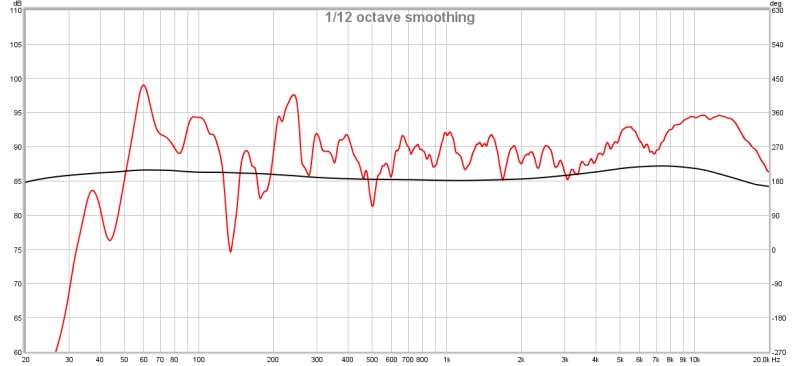
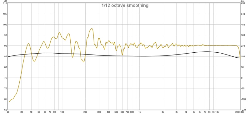
What is - Room or loudspeaker correction and why we would care about it?
First point every loudspeaker setup can’t produce equal sound pressure in all audio frequencies.
Second point if You have multi way loudspeaker system then mostly You will have passive crossovers what introduces phase shifts.
To overcome these problems we can use active digital filters to correct these errors.
Little bit theory about digital filter and requirements for such system.
First of all You need to choose one sample rate or else, every time You switch the sample rate You need to modify filter impulse response.
Second You need to know (understood) correlation between chosen sample rate and FIR filter length.
Simple equation for that is Fres = Sample rate / FIR Filter length. Fres is frequency resolution, for instance if You have 96kHz sample rate and 1024 Filter length then You will be able to correct frequencies with 96000/1024 = 93.75 resolution. As You can see frequency response at the low end is not enough.
Third point. Delay introduced by FIR filter. If You are using linear phase FIR filter Your output delay will be half of a chosen filter length multiplied by 1/sample rate.
I designed and tested such solution on FPGA based system (no CPU, only digital logic).
So what did I get - first prototype!:
*) FPGA - Cyclone III
*) FT2232 - communication with PC - load filter responses
*) up to 8192 FIR filter for each channel, can be increased
*) supports up to 96kHz sample rate, can be increased
*) desired impulse response can be imported from PC - for both channels separately
*) board have i2s input and output no additional converters are needed
*) computation is done on full precision
In picture below You can see high level block diagram
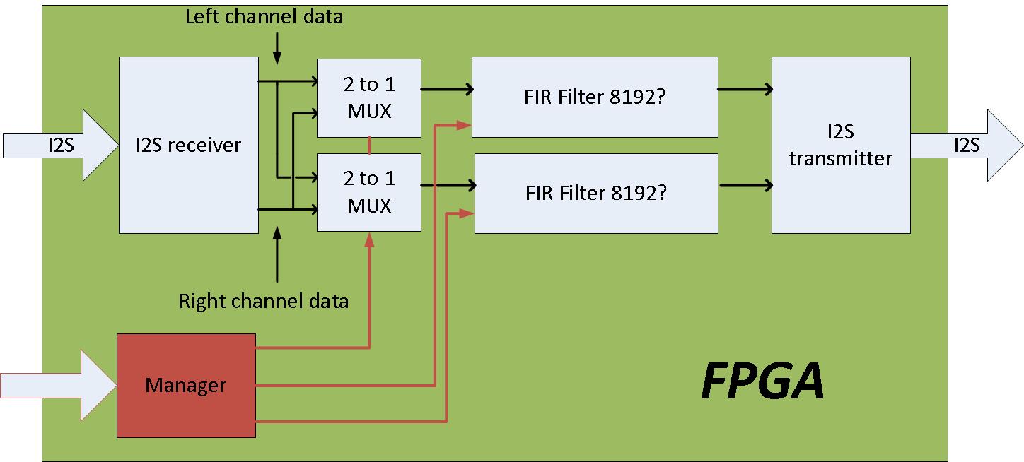
Multiplexers are placed to add more robust features, for instance splitting one channel data to more - useful when creating active crossover system.
To-Do list:
*) Learn how to control GPIO in RB Pi. Work with Python;
*) Design program which sends impulse response from RB Pi directly to FPGA;
*) IFFT implementation to calculate desired impulse response;
*) Some nice way to get measured data in RB Pi from loudspeaker;
*) GUI interface for creating/controlling FPGA?
*) New hardware design with more robust FPGA
If some points are not enough clearly explained, let me know, I will try to explain!
-Rinalds