Volumio Community
Rotary encoder mounting on gpio connectors
Help and Support
michel8166
April 20, 2024, 8:05am
2
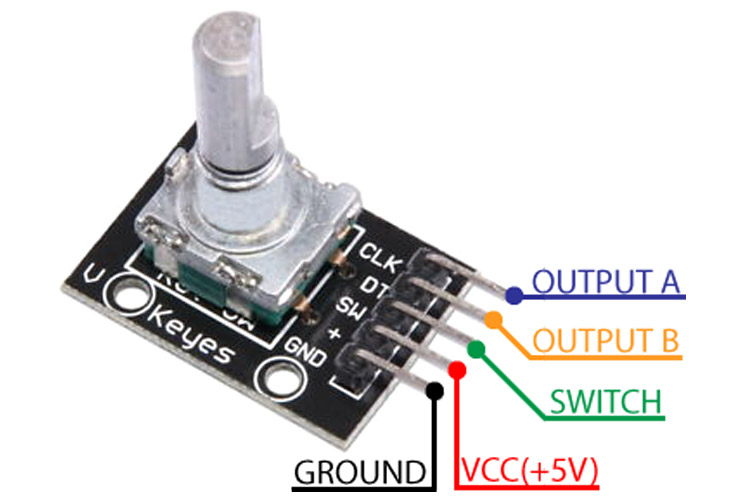
I use 3.3 volts.
KY-04-Rotary-Encoder-Pinout (1)
750×500 55.8 KB
show post in topic