Thanks - I appreciate your help, I’d been going round in circles until this evening
Oh and I have had the rotary encoder working fine using GPIO 5
Thanks - I appreciate your help, I’d been going round in circles until this evening
Oh and I have had the rotary encoder working fine using GPIO 5
Last thing to try, very basic.
All wires disconnected, GPIO button installed and active, set for gpio17, player playing, pin 17 open:
volumio@volumio:~$ gpioinfo gpiochip0
gpiochip0 - 54 lines:
line 0: “ID_SDA” unused input active-high
line 1: “ID_SCL” unused input active-high
line 2: “GPIO2” unused input active-high
line 3: “GPIO3” unused input active-high
line 4: “GPIO4” unused input active-high
line 5: “GPIO5” unused input active-high
line 6: “GPIO6” unused input active-high
line 7: “GPIO7” unused input active-high
line 8: “GPIO8” unused input active-high
line 9: “GPIO9” unused input active-high
line 10: “GPIO10” unused input active-high
line 11: “GPIO11” unused input active-high
line 12: “GPIO12” unused input active-high
line 13: “GPIO13” unused input active-high
line 14: “GPIO14” unused input active-high
line 15: “GPIO15” unused input active-high
line 16: “GPIO16” unused input active-high
line 17: “GPIO17” unused input active-high
line 18: “GPIO18” unused input active-high
line 19: “GPIO19” unused input active-high
line 20: “GPIO20” unused input active-high
line 21: “GPIO21” unused input active-high
line 22: “GPIO22” “mute” output active-high [used]
line 23: “GPIO23” unused input active-high
line 24: “GPIO24” unused input active-high
line 25: “GPIO25” unused input active-high
line 26: “GPIO26” unused input active-high
line 27: “GPIO27” unused input active-high
line 28: “PCIE_RP1_WAKE” unused output active-high
line 29: “FAN_TACH” unused input active-high
line 30: “HOST_SDA” unused input active-high
line 31: “HOST_SCL” unused input active-high
line 32: “ETH_RST_N” “phy-reset” output active-low [used]
line 33: “-” unused input active-high
line 34: “CD0_IO0_MICCLK” “cam0_reg” output active-high [used]
line 35: “CD0_IO0_MICDAT0” unused input active-high
line 36: “RP1_PCIE_CLKREQ_N” unused input active-high
line 37: “-” unused input active-high
line 38: “CD0_SDA” unused input active-high
line 39: “CD0_SCL” unused input active-high
line 40: “CD1_SDA” unused input active-high
line 41: “CD1_SCL” unused input active-high
line 42: “USB_VBUS_EN” unused output active-high
line 43: “USB_OC_N” unused input active-high
line 44: “RP1_STAT_LED” “PWR” output active-low [used]
line 45: “FAN_PWM” unused output active-high
line 46: “CD1_IO0_MICCLK” “cam1_reg” output active-high [used]
line 47: “2712_WAKE” unused input active-high
line 48: “CD1_IO1_MICDAT1” unused input active-high
line 49: “EN_MAX_USB_CUR” unused output active-high
line 50: “-” unused input active-high
line 51: “-” unused input active-high
line 52: “-” unused input active-high
line 53: “-” unused input active-high
Same again but pin 17 to ground:
volumio@volumio:~$ gpioinfo gpiochip0
gpiochip0 - 54 lines:
line 0: “ID_SDA” unused input active-high
line 1: “ID_SCL” unused input active-high
line 2: “GPIO2” unused input active-high
line 3: “GPIO3” unused input active-high
line 4: “GPIO4” unused input active-high
line 5: “GPIO5” unused input active-high
line 6: “GPIO6” unused input active-high
line 7: “GPIO7” unused input active-high
line 8: “GPIO8” unused input active-high
line 9: “GPIO9” unused input active-high
line 10: “GPIO10” unused input active-high
line 11: “GPIO11” unused input active-high
line 12: “GPIO12” unused input active-high
line 13: “GPIO13” unused input active-high
line 14: “GPIO14” unused input active-high
line 15: “GPIO15” unused input active-high
line 16: “GPIO16” unused input active-high
line 17: “GPIO17” unused input active-high
line 18: “GPIO18” unused input active-high
line 19: “GPIO19” unused input active-high
line 20: “GPIO20” unused input active-high
line 21: “GPIO21” unused input active-high
line 22: “GPIO22” “mute” output active-high [used]
line 23: “GPIO23” unused input active-high
line 24: “GPIO24” unused input active-high
line 25: “GPIO25” unused input active-high
line 26: “GPIO26” unused input active-high
line 27: “GPIO27” unused input active-high
line 28: “PCIE_RP1_WAKE” unused output active-high
line 29: “FAN_TACH” unused input active-high
line 30: “HOST_SDA” unused input active-high
line 31: “HOST_SCL” unused input active-high
line 32: “ETH_RST_N” “phy-reset” output active-low [used]
line 33: “-” unused input active-high
line 34: “CD0_IO0_MICCLK” “cam0_reg” output active-high [used]
line 35: “CD0_IO0_MICDAT0” unused input active-high
line 36: “RP1_PCIE_CLKREQ_N” unused input active-high
line 37: “-” unused input active-high
line 38: “CD0_SDA” unused input active-high
line 39: “CD0_SCL” unused input active-high
line 40: “CD1_SDA” unused input active-high
line 41: “CD1_SCL” unused input active-high
line 42: “USB_VBUS_EN” unused output active-high
line 43: “USB_OC_N” unused input active-high
line 44: “RP1_STAT_LED” “PWR” output active-low [used]
line 45: “FAN_PWM” unused output active-high
line 46: “CD1_IO0_MICCLK” “cam1_reg” output active-high [used]
line 47: “2712_WAKE” unused input active-high
line 48: “CD1_IO1_MICDAT1” unused input active-high
line 49: “EN_MAX_USB_CUR” unused output active-high
line 50: “-” unused input active-high
line 51: “-” unused input active-high
line 52: “-” unused input active-high
line 53: “-” unused input active-high
mmmm, no idea’s anymore.
For whatever reason it’s not registering GPIO17, let’s see if someone else ahs any suggestion.
Thanks, I appreciate your time and help, very kind of you.
sorry but I can’t give much help regarding this problem, I have no clue on why the GPIO17 is not registered
I only noticed one possible issue on the connection diagram:
I see three different push-button connected in parallel to the same pin, with three different functionalities assigned.
This won’t work, one pin can be used for only one trigger action, because the pin won’t be able to distinguish which button out of the three has being pressed.
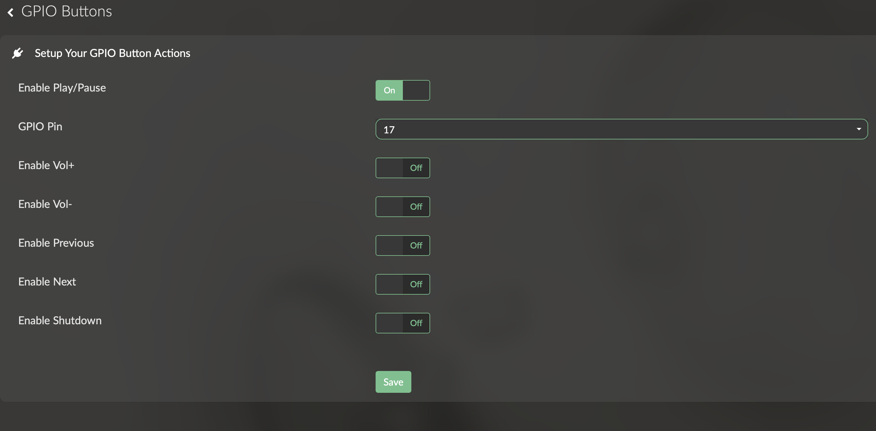
Please post a screenshot of your setting of the GPIO Buttons plugin, the issue might be there.
This drawing was for a specific existing keypad, where PLAY/STOP/PAUSE mimic volumio toggle, hence these three are combined.
But even with a bare wire between GND-GPIO17, the GPIO is not registering. So I have no idea’s anymore.
Good morning. Yes the schematic was purely to show the pull down arrangement on the input channels - I have only one switch on GPIO 17. I am going to remove my DAC (IQaudIO DAC Plus) just in case that’s upsetting things or there is an issue with the header - unlikely I know as both the rotary encoder and GPIO control work, but I can’t think of anything else to try. Then if necessary I’ll just load a standard pi operating system to the board and check the GPIO operation from the Pi OS. If nothing works I suppose I’ll just buy a new Pi5.
There doesn’t appear to be anything wrong with my Rpi5, installed RPI OS ran a simple python program using gpiozero using gpio17 to switch a led on gpio14. Worked perfectly and showed up in gpiomon
| line 13: GPIO13 unused input active-high | |
|---|---|
| line 14: GPIO14 lg output active-high [used] | |
| line 15: GPIO15 unused input active-high | |
| line 16: GPIO16 unused input active-high | |
| line 17: GPIO17 lg input active-high [used pull-up] | |
| line 18: GPIO18 unused input active-high |
So I’m completely lost with why GPIO Buttons won’t work for me.
As a final test I have done a clean install on a USB 2.5” SSD using the hdmi0 as the output. I have installed and enabled GPIO Buttons, GPIO Control and Rotary Encoder II.
GPIO Buttons on GPIO 26 - Enable Play/Pause
GPIO Control on GPIO 14 – Led On Play, Led Off on Stop
Rotary Encoder II – Pin A GPIO 5, Pin B GPIO 6, Pushbutton GPIO 27 (short press Play, long press Random, double press Stop)
The GPIO button(26) does not show in gpiomon, other pins show correctly – see below
Encoder works perfectly with the Play led, looking in the log, I can see the encoder push button triggers an entry each time. As a test, I substituted the encoder pushbutton for the switch and that worked fine so I know my hardware is correct.
Looking at the log, there is no event triggered when the switch is pressed. It’s as if the plugin isn’t installed, but it is and there were no errors during the installation and the plugin management screen is all green.
gpiochip0 - 54 lines:
line 0: “ID_SDA” unused input active-high
line 1: “ID_SCL” unused input active-high
line 2: “GPIO2” unused input active-high
line 3: “GPIO3” unused input active-high
line 4: “GPIO4” unused output active-high
line 5: “GPIO5” “rotary@5” input active-high [used]
line 6: “GPIO6” “rotary@5” input active-high [used]
line 7: “GPIO7” unused input active-high
line 8: “GPIO8” unused input active-high
line 9: “GPIO9” unused input active-high
line 10: “GPIO10” unused input active-high
line 11: “GPIO11” unused input active-high
line 12: “GPIO12” unused input active-high
line 13: “GPIO13” unused input active-high
line 14: “GPIO14” “?” output active-high [used]
line 15: “GPIO15” unused input active-high
line 16: “GPIO16” unused input active-high
line 17: “GPIO17” unused input active-high
line 18: “GPIO18” unused input active-high
line 19: “GPIO19” unused input active-high
line 20: “GPIO20” unused input active-high
line 21: “GPIO21” unused input active-high
line 22: “GPIO22” unused input active-high
line 23: “GPIO23” unused input active-high
line 24: “GPIO24” unused input active-high
line 25: “GPIO25” unused input active-high
line 26: “GPIO26” unused input active-high
line 27: “GPIO27” “KEY_POWER” input active-low [used]
line 28: “PCIE_RP1_WAKE” unused input active-high
line 29: “FAN_TACH” unused input active-high
line 30: “HOST_SDA” unused input active-high
line 31: “HOST_SCL” unused input active-high
line 32: “ETH_RST_N” “phy-reset” output active-low [used]
line 33: “-” unused input active-high
line 34: “CD0_IO0_MICCLK” “cam0_reg” output active-high [used]
line 35: “CD0_IO0_MICDAT0” unused input active-high
line 36: “RP1_PCIE_CLKREQ_N” unused input active-high
line 37: “-” unused input active-high
line 38: “CD0_SDA” unused input active-high
line 39: “CD0_SCL” unused input active-high
line 40: “CD1_SDA” unused input active-high
line 41: “CD1_SCL” unused input active-high
line 42: “USB_VBUS_EN” unused output active-high
line 43: “USB_OC_N” unused input active-high
line 44: “RP1_STAT_LED” “PWR” output active-low [used]
line 45: “FAN_PWM” unused output active-high
line 46: “CD1_IO0_MICCLK” “cam1_reg” output active-high [used]
line 47: “2712_WAKE” unused input active-high
line 48: “CD1_IO1_MICDAT1” unused input active-high
line 49: “EN_MAX_USB_CUR” unused output active-high
line 50: “-” unused input active-high
line 51: “-” unused input active-high
line 52: “-” unused input active-high
line 53: “-” unused input active-high
Thanks for the fast response supercrab.
Can’t seem to find the function in system or in the plugins, I’m running version 3.611 and the latest version of the app, and using the classic layout, has it been added since then?
I have a pi 5, and I am trying to get GPIO buttons plugin working.
I tried pulling the pin high, then tried pulling it low, with no events triggered within Volumino, the button’s plugin does not see the state change no matter what I try. I verified that the state is changing with my DMM.
My Goal is
GPIO24 for Track Next. Using GPIO Buttons Plugin (Not Working)
GPIO25 for Track Previous. Using GPIO Buttons Plugin (Not Working)
GPIO12, GPIO13 Rotary Volume Up and Down (Working)
GPIO6 Rotary Button Press for Mute toggle and Play on long press. (Working)
Also add Power On Of at some point.
I have been searching off and on for a couple of days, and about the only information I could find was that the PI5 GPIO is different from previous pi versions. Or that it is compatible with PI5.
The Rotary Encoder plugin worked on the first try.
Hi all,
I’'m trying to get some physical switch to work with this plugin and ran into a strange one :
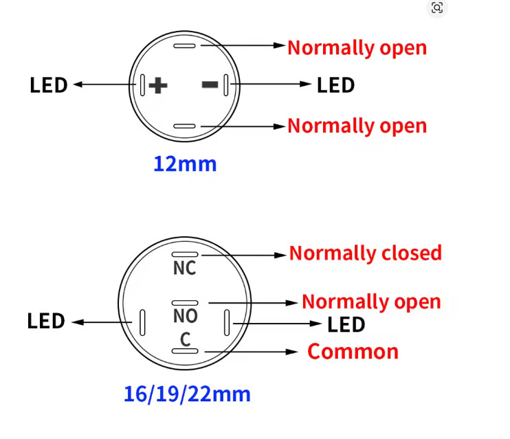
I’m using 2 type of switch (different size, only for design purpose) and while I can get the one with 4 wires to work right away, I can’t seem to get the second type to do anything when pressed (I tried both NO or NC wiring).
I tried the 2 type of swithc on the same GPIO, and only the one with the 4 wires is working. They are both rated 3-6V
Anyone already ran into this one or have an idea where I could start to investigate?
Thanks!
These are 2 different kind of switches.
So connecting the 2nd switch between C and NO behaves the same as the first
Thanks for the fast answer ![]()
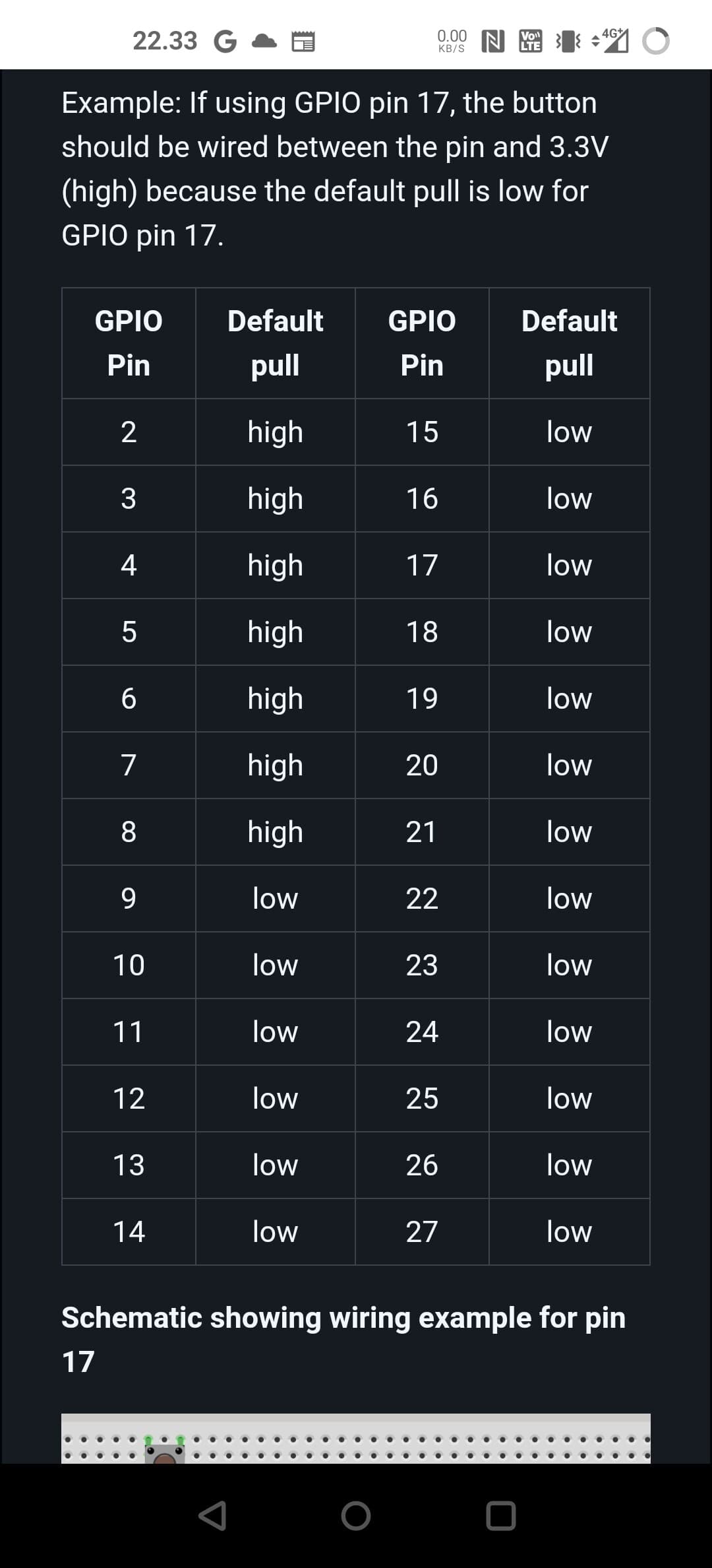
Just figured it out … I guess I was mislead by this table earlier in the thread :
I was connecting my switch between the GPIO 17 and the 3.3V, because that what I understood from the table.
But when I connect my switch between GPIO 17 and GND, tada!, it works ![]()
Thanks again for clarifying the switch connections for me, definitively helped me figure it out.
Not sure if this is the correct place for ths but here goes….
Using the GPIO-buttons plugin with Volumio 3 I used to ‘edit’ it for my particular set up
For example;
I would replace;
GPIOButtons.prototype.shutdown = function() {
this.logger.info(‘GPIO-Buttons: shutdown button pressed\n’);
this.commandRouter.shutdown();
};
with;
GPIOButtons.prototype.shutdown = function() {
const endPoint = { ‘type’:‘plugin’, ‘endpoint’: ‘user_interface/randomizer’, ‘method’: ‘randomAlbum’ };
socket.emit(‘callMethod’, endPoint);
};
which worked well.
It doesn’t work with Volumio4 though.
Has anyone any pointers towards a working ‘edit’ for Volumio 4?
Hi @Old_Duffer ,
I raised the same with the Rotary Encoder. Seems related to V4.
@nerd Any idea/suggestion?
Dear Volumionauts,
I investigated the WebSocket issue affecting gpio-buttons (and likely rotary-encoder) on Volumio 4. Here are the findings:
Problem
Volumio 4’s package.json declares socket.io 2.3.0, but the actually installed version is 1.7.4:
volumio@hanger:~$ cat /volumio/node_modules/socket.io/package.json | grep version
  "version": "1.7.4",
The gpio-buttons plugin specifies "socket.io-client": "^2.3.0" which npm resolves to 2.5.0. This creates a protocol mismatch:
Parser 3.x cannot decode parser 2.x messages. When the server sends any response (pushState, etc.), the client crashes:
Error: invalid payload
    at decodeString (socket.io-parser/index.js:355:13)
The callMethod actually reaches the server and executes - logs confirm this. But the client socket dies on the response, so all subsequent button presses fail silently.
Why it worked on Volumio 3
Node 14 likely had different npm resolution behavior, or the installed socket.io-client version happened to match. The key issue is the mismatch between declared (2.3.0) and actual (1.7.4) server versions. Alternatively - module declarations in package.json.
Fix
Change package.json from:
"socket.io-client": "^2.3.0"
To:
"socket.io-client": "1.7.4"
Tested and confirmed working - no more crashes, pushState events received properly.
Affected plugins
Any plugin using socket.io-client ^2.x will have this issue:
@tomatpasser @Darmur @Wheaten - Do you want to push this fix, or shall I submit a PR? Happy to help either way.
Kind Regards,
Not that I am not willing, but pretty sure I will break things.
Confirmed with Rotary Encoder. it works.
Weird as I use 2.3.0 with success in